Project update 2 of 9
Antenna Efficiency Tuning
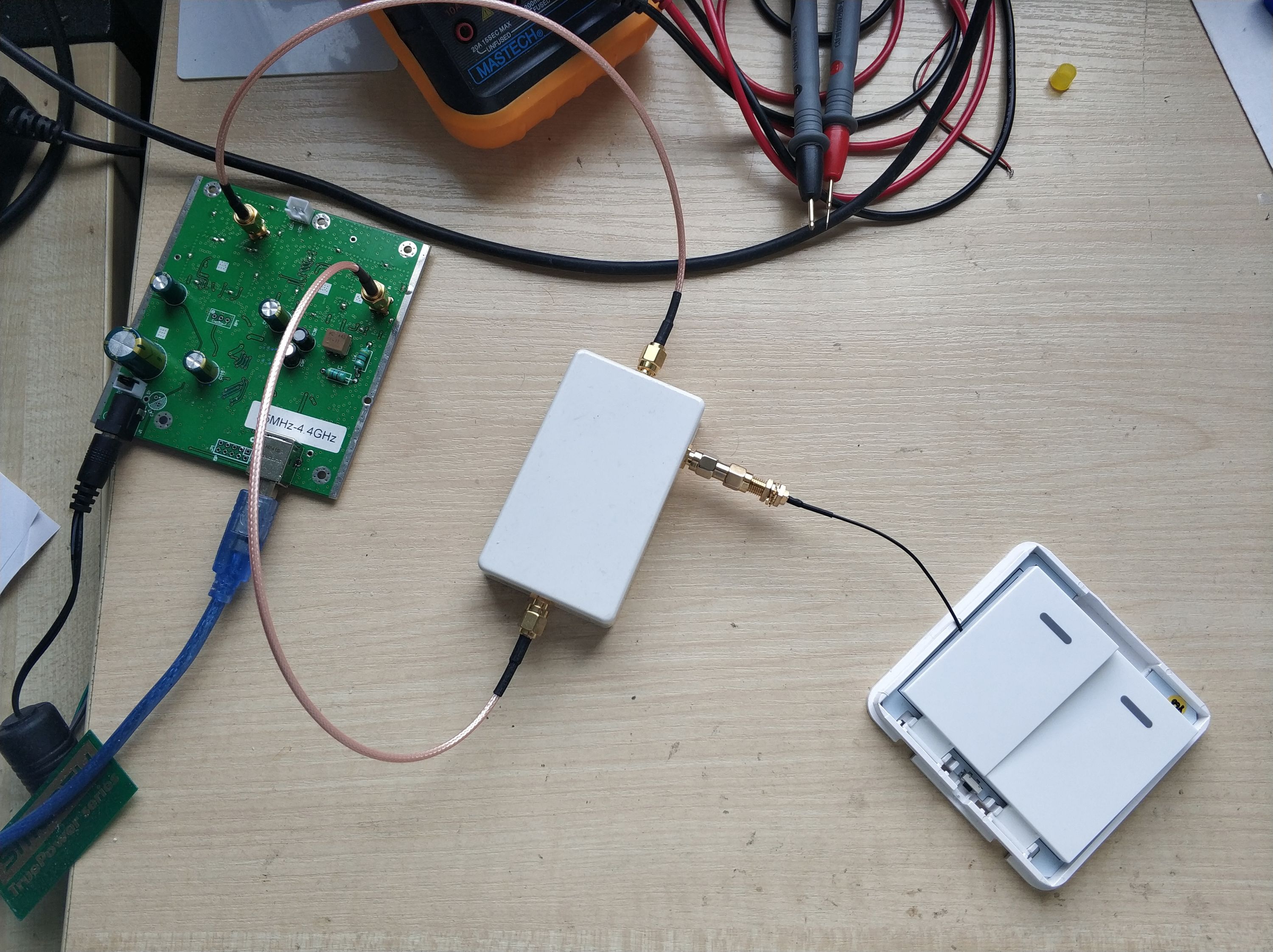
The number one challenge for compact radio-controlled device creation is PCB antenna efficiency tuning. Antennas with SMA connector feeder could be used for an easy workaround but they are bulky and hard to put inside enclosure. Most DIY projects use wire antennas. There are lots of pros with this solution, but also many cons. It is preferred often because it costs nothing and it works in most cases! However, the cons are that it does not work as well and sometimes does not work at all. Spending hours trying to put antenna into device compartment is real pain. The when you finally get everything properly packed inside - the device transmits nothing. Agrhh all the signal went into the nearby ground plane or the wire starts resonating at completely different frequency.
Coiled antennas are similar to PCB antennas, requiring the counterpoise ground plane. They require efficiency tuning similar to PCB antennas. We used PCB antennas since they are more compact and easy to produce. Our goal is to make the easySwitchBox device work across the same distance as bulky SMA antennas.
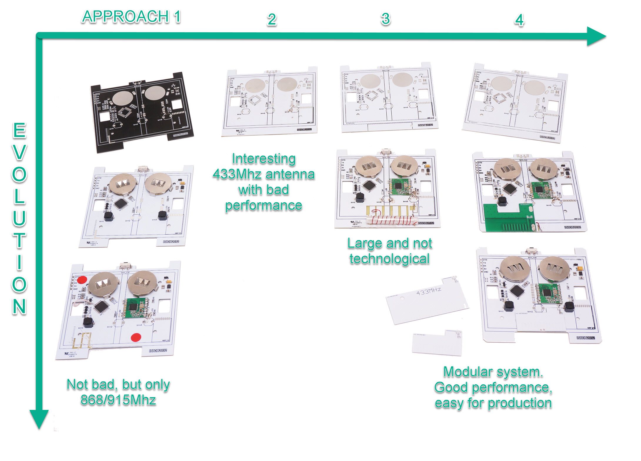
PCB antenna efficiency tuning turns out to be a difficult equation for many creators. However, it can be solved relatively easy if the device and antenna are designed as one piece from the very beginning. Lets say you have the battery powered device, enclosure, and antenna dimensions determined. The connected thing is being built around the antenna’s necessary counterpoise ground plane and gap between them. The counterpoise ground plane of the device is essential part of the antenna.
Then tuning starts:
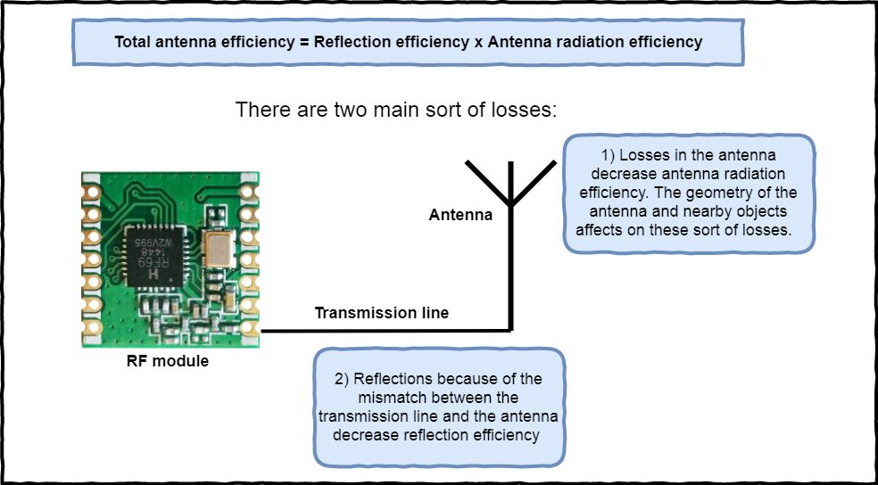
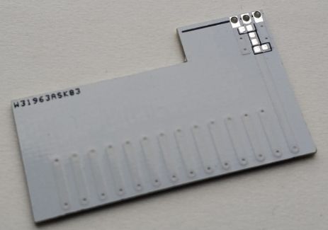
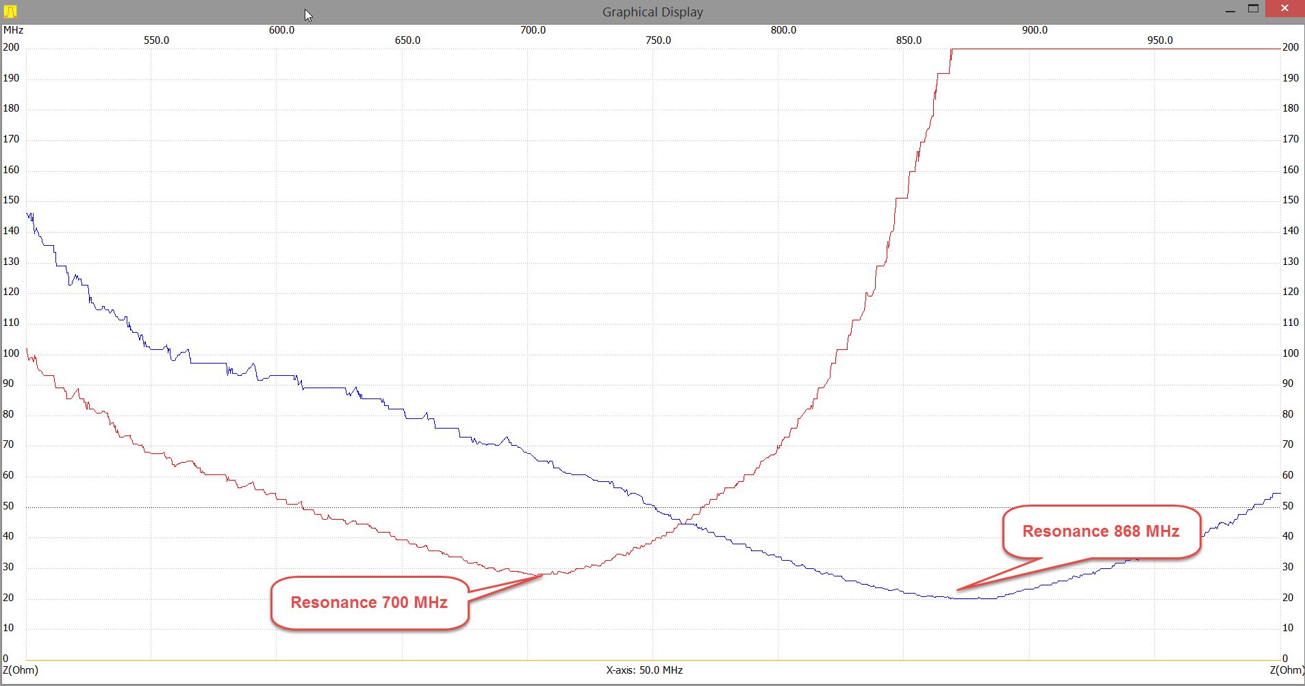
We should Increase antenna radiation efficiency and match transmitter with antenna to increase reflection efficiency. Antenna radiation efficiency is maximum when antenna resonance frequency is equal to the transmission radio frequency. We can find the resonance frequency as minimum of the antenna impedance. We used prototype antenna modules with longer antennas, so we could cut it to decrease resonance frequency.
In the below graph you can see the impedance vs frequency curve of our antenna module before resonance tuning (red line) and after cutting the antenna to the appropriate length (blue line).
The second step is to estimate reflection efficiency. It is SWR measurement. If transmitter is perfectly matched with antenna SWR = 1, so 100% of radio power is transmitted to the antenna. If SWR = 2 then 89% of power is transmitted, SWR = 3 is equal of 75% of transmitted power and so on. The rule of thumb is achieving SWR less than 2.
The chart below is a comparison of SWR for the easySwitchBox with different antennas.
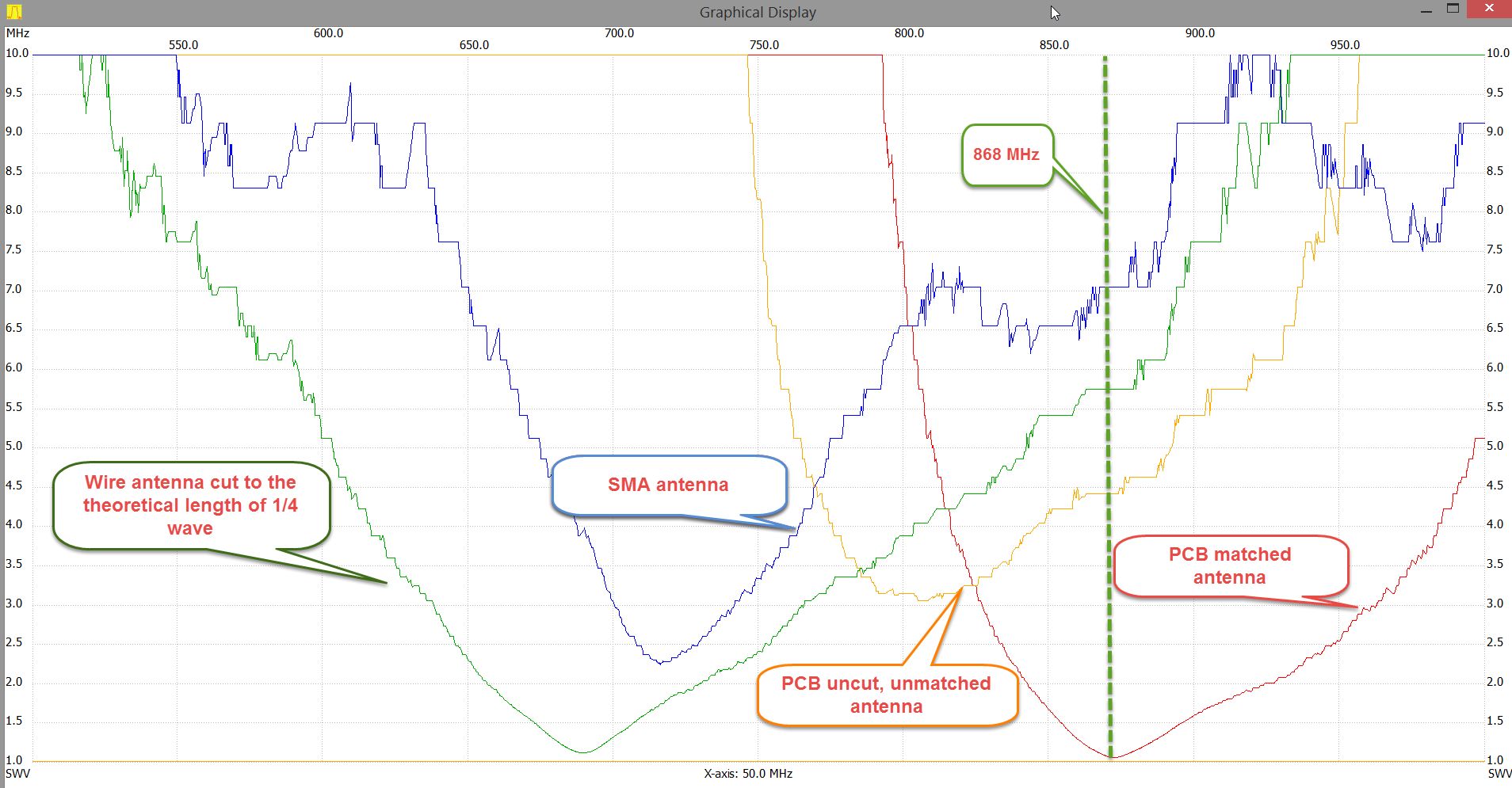
Green line – simple 9cm wire. Interesting thing – SWR is perfect but the frequency is not 868Mhz because the ground plane and wire position are far from ideal monopole.
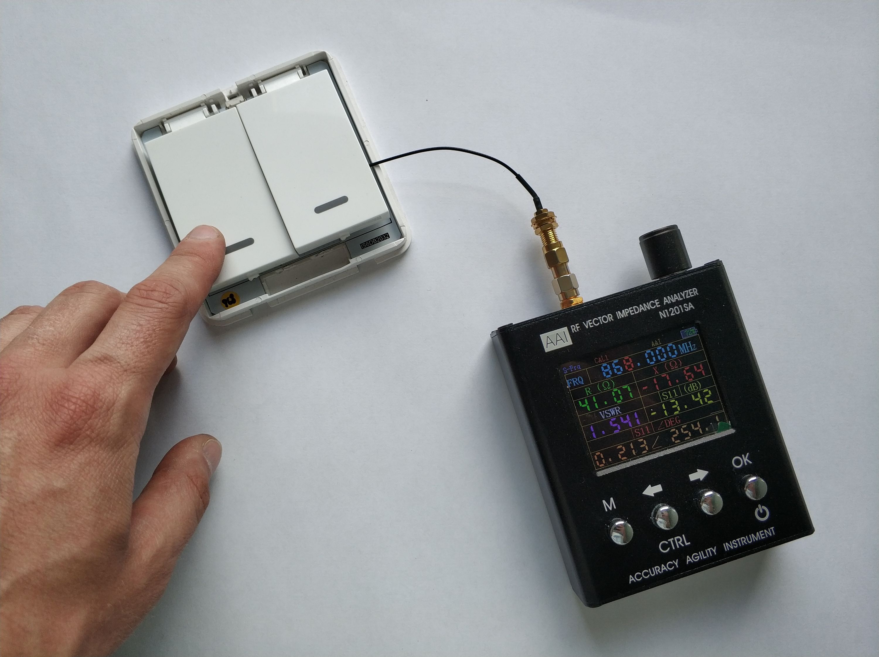
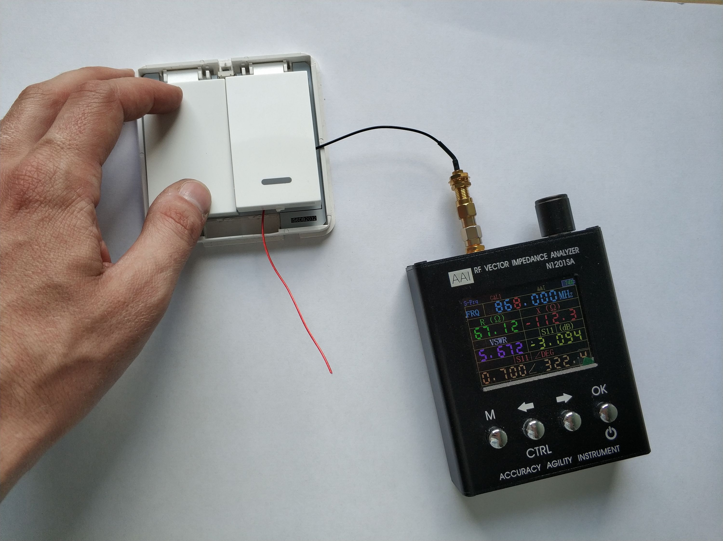
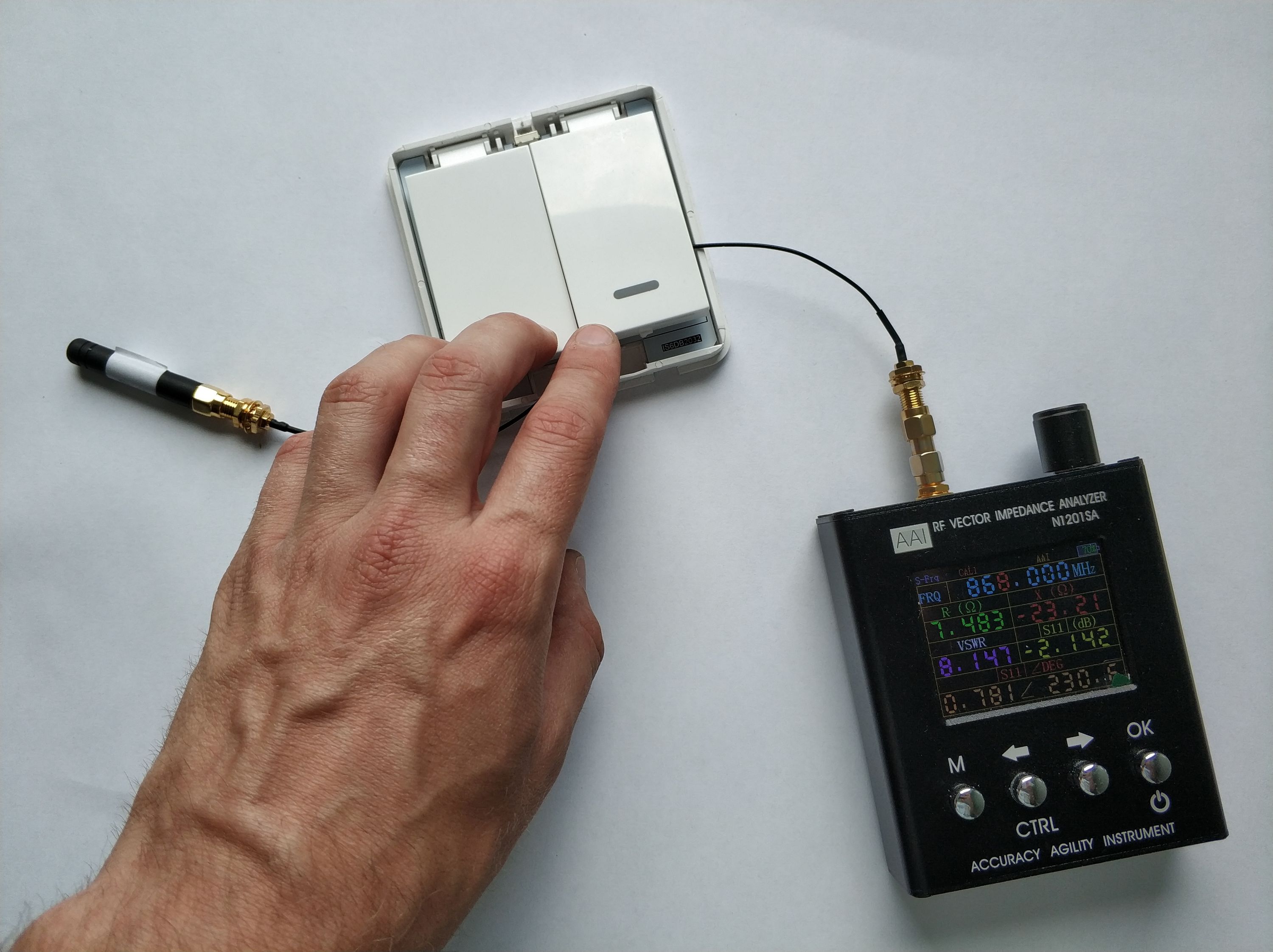
Matched PCB antenna:
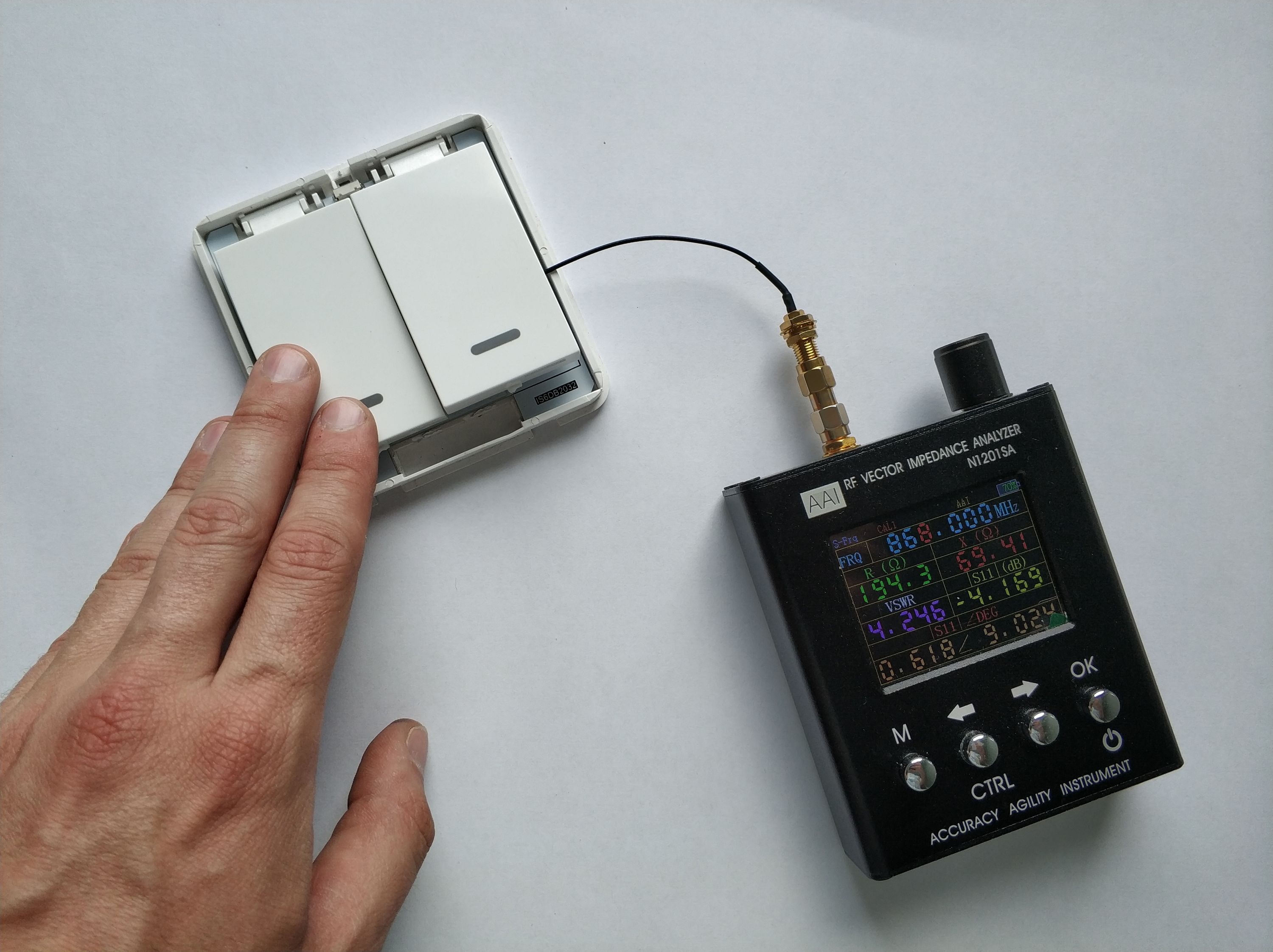
Unmatched PCB antenna:
Wire antenna:
Stock SMA antenna:
In real life, we measured followed distance for low power RFM69CW module:
- Unmatched antennas gave us 200 meters (656 ft.)
- Wire antenna gave us 220 meters (720 ft.)
- Matched antennas gave us 350 meters (1150 ft.)
- SMA antenna 300 meters (985 ft.)