Project update 52 of 75
2.7.5 HDMI Review Status; 3D Printer MK2 Reaches 3rd Prototype
by Luke Kenneth Casson Leighton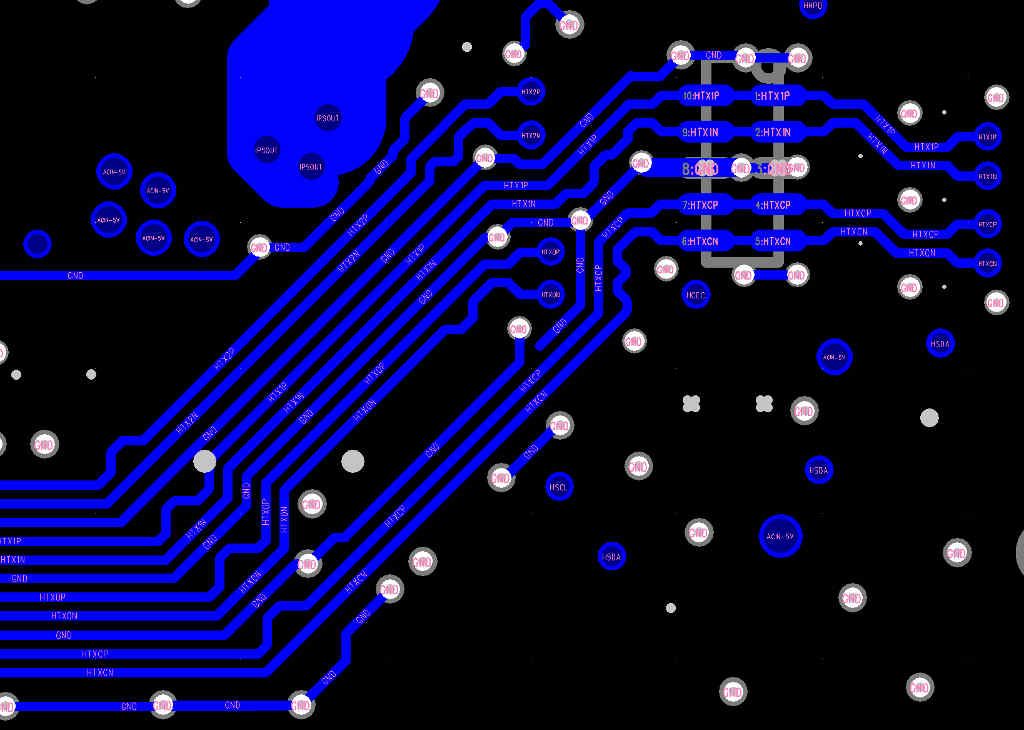
HDMI Recommendations
I thought, really, it would be best to just simply summarise the progress so far on the rhombus-tech wiki for the HDMI analysis. It’s been… extremely detailed, and extremely thorough, with the resultant summary being after several revisions and mistakes were noted, even after considerable research and reading.
I feel that we’re now mostly through it, so I can now admit publicly (because Richard and the others who have helped out will also be reading this): I didn’t want to mention that pretty much the entire project - the delivery of the EOMA68-A20 Cards in particular - has been held up whilst we undergo this review, when you are effectively volunteering your time - with no expectation of financial reward - on a libre project. No pressure or anything, then. Which is the whole reason why I haven’t said anything, despite this being the last time that I will attempt to get this ultra-specialist Mid-Mount Micro-HDMI connector (0.2 mm wide pins, only 0.2 mm separation between them) working.
Instead, to even say a simple "thank you" to Richard and the others who have provided their time, expertise, and encouragement would be a huge understatement. There’s no way that I would have done such a thorough analysis on my own: I don’t have that kind of mind-set. So your efforts have helped greatly increase the chances that we will get a working Micro-HDMI connector.
On that note: I contacted Mike a couple of days ago and sent him the gerbers for a low-cost (1" sq, two-layer) test PCB, so that we can try putting 10 of the JAE DC3 HDMI connectors through the actual production process of a reflow oven (rather than try to put them on with a prototyping hot-air gun tool). If you recall, from the last update: the 0.2 mm wide vias coming up in the middle of the tiny 0.2 mm x 0.6 mm pads for the connector’s pins sucked all the solder down, and the 0.2 mm wide pins simply had nothing to stick to. Mike actually apologised for not being in touch for months as he has been so ridiculously busy. I explained to him that it was fine, and that it was actually all good synchronicity, that we had to do a very careful and comprehensive review.
There was an extremely good suggestion which came up just a bit too late: to try to put in 19-pin FPC connectors and separate out the Micro-HDMI connector onto a separate (tiny) PCB, using a much more standard top mount connector. The advantage being: the top-mounted connector would be at the right height because it would be lower than the main PCB inside the 5 mm case. If this idea had come up even six months ago - particularly when I was in Shenzhen - it could have been considered, as I could have sourced the components. However space is extremely tight: I am not certain that the proposed FPC connectors would even fit.
All of this care and attention - a bit late - is down to the fact that each revision costs us around $2,000 USD for 10 samples, and adds a five- to eight-week delay just for the PCB manufacturing and PCB assembly. Contrast that with the hell-for-leather rapid prototyping below…
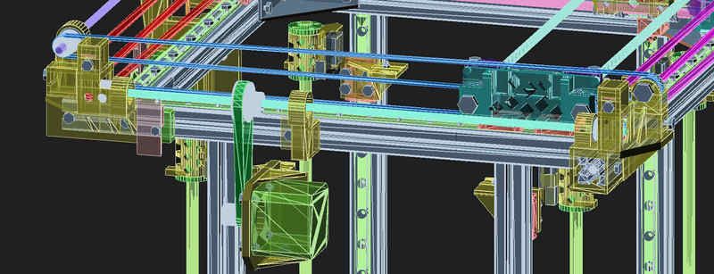
3D Printing "Maximising the Units Per Hour Per Dollar" Metric
There have been some fascinating and absolutely invaluable discussions on both the "Cheap and Cheerful" Taobao wannabe knockoff and on the Riki200 discussion thread.
On both I am deliberately making an effort to document the successes and failures, so other people can learn from them. If I am honest, however, I have to include myself in the "Group Of People Doing The ‘Lurn’in", y’ken. It’s not laziness to rush ahead where fools dare to tread, I swear: I just like finding things out as fast as possible, as a substitute for "careful calculations and thought." I do, however, feel incredibly sheepish at having publicly blundered about not just once but three or possibly even four times, so I am extremely grateful to the people who have contributed both on the mailing list, on StackExchange, and also on the forum, doing detailed design analysis or comprehensive actual physics equations.
But the one thing that I really wanted to emphasise here is the huge difference between the 3D printing world and the PCB CAD and PCB production world. It hasn’t done my health much good, but basically I can sit here doing CAD design for a week, spend a couple of days 3D printing a few bits of plastic costing about \$5 to \$10 USD a time, and try it out by using some tools that I bought from a hardware store 100 metres down the street from my former apartment in Den Haag. $5 to \$10 vs \$2,000. One to two weeks round-trip per design effort vs 10 to 15 or often even longer.
So now you know why I feel like the mad headlong rush testing and improving two 3D printers simultaneously is not so mad after all.
But why two at the same time? Remember: the metric driving this is "units per hour per dollar" (thank you to Josef from the reprap forum for encouraging me to change that from the original "mm / sec / $" metric). So there are two ways to hit that kind of target: firstly to only use extremely common, cost-effective, and preferably mass-produced parts, putting together a tried-and-tested design that, although it has severe limitations that would give a professional mechanical engineer an absolute heart attack, overall still does a fair job of not falling to bits.
Cheapness equals cheerfulness. The ant swarm. One dead ant does not a dead colony make.
The second way is to try to up the intelligence behind the use and selection of the components somewhat. Actually do some design analysis. Think, "if this part is included and it costs 50% more but increases the metric by 60%, it’s a good deal: keep it." So for example: the use of a pulley system. A pulley system is well-known for doubling the amount of pulling-power by introducing something called a "Velocity Ratio". For a velocity ratio of two (a single pulley) you have to pull twice as fast but with only half the force.
What is not so well known - not so widely discussed - is that the amount of "stretch" in the rope (or whatever is used) is also halved. So if you use pulleys in a 3D printer to move the carriage, the amount of "stretch" that occurs in the belts due to acceleration is (friction and idler play not taken into consideration) halved. And what that in turn means is that you could - theoretically - double the speed of the movement of the carriage without changing the acceleration firmware numbers and you might not actually get the "ringing" effect so commonly seen on corners at high acceleration and speed settings:
Basically what’s happening here is a combination of a lot of factors:
- The frame is probably about as rigid as a pudding. Consequently,
carriage movement causes it to rock and sway, and it vibrates the entire print head relative to the printbed as a result. This is best demonstrated on pretty much absolutely any Delta 3D Printer, with the notable exception of the Fisher.
- The extruder is almost certainly not properly attached to the
carriage, and the whole carriage assembly is probably not in the mass-geographic centre between the rods (or rails). So a change in direction makes the entire extruder (and carriage) bounce sideways and upwards, or both, or simply causes the plastic to twist, or the rods, or causes the bearings to bounce about (particularly if they or the rods are out of spec) - so many factors here - and that all adds up to "ringing"…
- The belts are slack, or the acceleration setting is so high that it
doesn’t matter how tight the belts are. This is the usual source of ringing, but, as can be seen above, it is not the only one.
So, whilst we have one factor under consideration - to double up the belts with a pulley in order to use two belt sections to share the accelerative stretching force between them - it’s certainly not the only factor, by a long shot. It’s no good using a great pulley system and attaching it to a damp pudding for a frame, for example, but, in the spirit of the target metric, it’s no good substituting cheap-and-cheerful 2020 extrusion for massive solid 100kg blocks of steel, either.
The point is: unlike reducing the component cost and count but still having acceptable speed, with attempting to increase the number of units that any given single printer can produce per hour, we actually have to think.
So, for example, instead of stiffening the frame with expensive PVC, PC, FR4, or Lexan bracing (or more 2020 extrusion which has to go into costly 45° angle specialist brackets) I’m looking to cut up sub-$0.50 USD mild steel 2 mm thick coat hangers! Assemble a gantry in each corner, attach two pieces in a cross in every face of the cube, and then use a 50 mm M5 bolt to lever them apart, creating equal tension on all four triangles of the cross, neatly pulling every piece of 2020 extrusion in and placing them under the required compression to be able to call this "an actual frame" instead of.. say… a Traditional British Christmas Favourite edible food substance full of lard and sugar.
But ultimately the point about the belts is: what would you otherwise do to the belts in order to get the same effect as doubling them up with a pulley? Well, you could use 10 mm wide belt that’s normally used with NEMA23 steppers, instead, but that’s not as common in the 3D printing world: it’s more expensive, and so are the gears, and the idlers. You could use two sets of belts running on parallel paths, but now you have a double stack of idlers, which means greater separation between X and Y moving parts, which could have ramifications for the stability (holding the carriage rigid). A huge number of factors to consider, where we could just add two extra good quality idlers, use an extra 350 mm of belt and achieve the same effect… but importantly in the same physical space. As an experiment, it’s worth trying.
There is, however, another side-effect of using the pulleys, and it’s related to the extra velocity. Someone very kindly pointed out that on this latest (3rd) concept the use of a closed loop with a 2:1 ratio (40 teeth to 20 teeth) in combination with the 2:1 velocity ratio actually takes the NEMA17 motors outside of their rated maximum RPM curve, and even if you keep it just under that, at the maximum RPM the available torque is only a fraction of what it is at lower RPMs.
Whoops.
So we had a bit of a lairy moment on the forum, and came up with a plan: how about making it possible to unplug the NEMA17, turn it round, plug it back in, and loop the closed-loop belt onto a 1:1 ratio (20 teeth to 20 teeth)? Or if you took it out entirely and replaced it with an 84 oz.in, 2 A Monster NEMA17? So here are the two possible scenarios:
- Run really slowly, use the new E3D-Online 0.15 mm nozzles but
note that they say "use 0.9 degrees per step NEMA17 motors due to micro-stepping artefacts." Would it not be fantastic if you could get a 5:1 mechanical advantage by using a 40T to 16T (2.5 to 1) plus a velocity ratio of two from some pulleys, for a total of a TEN to one gear ratio over a standard 3D printer?
- Run really fast: use those 84 oz.in, 1.9° / step Beasties, use
the direct 1:1 loop but still get a 2:1 mechanical advantage from the pulley system.
Would it not be fantastic to have the option to do both those completely different types of jobs, in one single 3D printer? And to go one up on that by using a Flex3Drive to get better than the advantages of both the bowden and direct-drive worlds? (The Flex3Drive combines a 40:1 wormdrive with an automotive-grade flexible driveshaft.)
So, whilst the goal here is to design a 3D printer that people can back to help fulfill the second half of this current campaign, it would almost be a travesty to only have the cheap-and-cheerful option available, even if the second experimental design turns out to need components that cost so much they actually take it outside of its original design strategy. Particularly when that cheap and cheerful option - so far - has to use the sadly tried-and-tested RAMPS 1.4 from China because it’s so ridiculously low-cost (under $20 including the god-awful A4988 Polulu drivers: whoever thought it would be a good idea to push 30 Watts down a single 2.54 mm pin to a postage-stamp-sized PCB needs their head examined).
On that last note: If anyone knows of any libre 32-bit 3D printing controller boards (i.e., are not criminally infringing copyright or can be easily reverse-engineered in a couple of days), which are not more expensive than the entire combined BOM for the Taobao clone, please do let me know. It truly is a travesty that the RAMPS 1.4 + Arduino 2560 + four A4988 dreadful Polulu postage-stamps can be had for under $20 in volume, when the absolutely superb DuetWIFI costs more in Europe and the USA than an entire serviceable 3D printer sourced from China.