Project update 10 of 27
Why Arduino Due?
We selected Arduino Due for ERASynth for a number of reasons: Its processing power, number of available hard SPI LE pins, availability of a many GPIO pins, and its natural integration with the ubiquitous Wi-Fi module ESP8266.
Powerful MCU
When we started the design of ERASynth, we could use any of the many open source projects for the control of our signal generator project. We evaluated our options and realized Arduino Due had the enough horsepower to support all of the calculations. CPU power was an important metric for us, because we had set out to create an agile signal generator. When you are aiming to achieve frequency-switching speeds under 100 µs, you do not have a lot to waste on the calculations. With its 84MHz ATSAM3XE, Arduino Due was the perfect choice for ERASynth.
Number of Hard LE Pins
Serial Peripheral Interface (SPI) is a serial protocol that uses four lanes for duplex communication between a master and a slave device. When it comes to PLL synthesizers, SPI is now the industry standard. Almost all of the state-of-the-art PLL ICs provide three or more pins for configuration by a host microcontroller using the SPI protocol. The naming on the pins can vary but the functionality stays the same. Here is a list of the SPI pin names encountered in PLL datasheets:
- Master Out Slave In: MOSI, DATA, SDATA, SDO, SDIO
- Master In Slave Out: MISO, SDI, SDIO, MUXOUT
- Clock: CLK, SCLK, SCK
- Slave Select: SS, CS, LE, SEN, CSB
Current revision of ERASynth made use of four different PLL ICs: ADF4002, HMC830, ADF4356 and LTC6945. The final prototype will use ADF4002 and LMX2594. All of these ICs require SPI communication for programming. Arduino Due provides one SPI bus with three hard LE pins. Hence, one can program up to three separate PLL ICs using the Arduino Due. Three hard LE pins are sufficient for most purposes. In the case where there are more than three slave devices (as in the case of ERASynth rev2), soft LE pins can be used. Soft LE pins are normal GPIO pins used for slave selection. There is a significant amount of delay associated with soft LE pins, i.e., SPI transactions using hard LE pins are much faster compared to soft LE transactions. For an ultra-fast RF synthesizer as ERASynth, availability of hard LE pins in Arduino Due were advantageous. We used all three hard LE pins for the ICs for which speed was crucial. HMC830 (tunable reference generator), ADF4356 (main VCO), and LTC6945 (main PLL) were programmed using the hard LE pins. Here is a screen short of the SPI transactions for a frequency of 4 GHz:
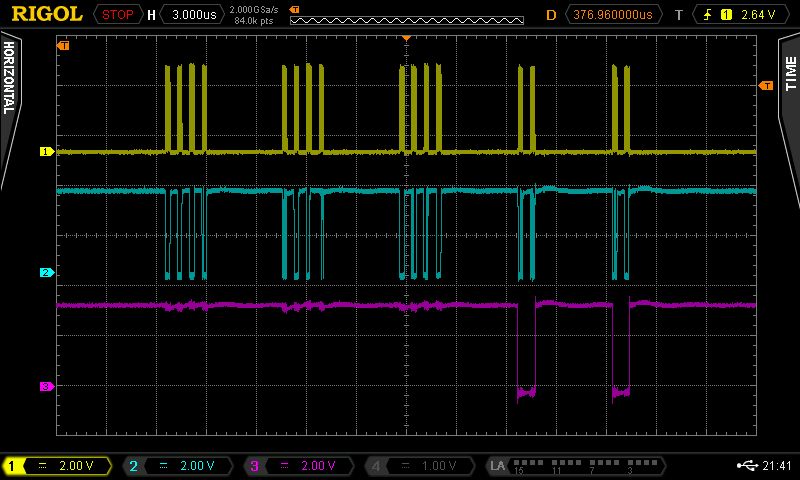
As you can see in the figure above, one frequency change command requires 16 bytes of SPI transaction. We were able send 16 bytes in less than 30 µs.
A Plethora GPIO Pins
Wideband and high dynamic range RF circuits utilize many control elements such as switches and attenuators to provide the wide bandwidth and dynamic range. In the design of ERASynth, there are multiple switches and several attenuators requiring more than 20 GPIO pins. Luckily, Arduino Due provides more than enough GPIO pins.
Natural Integration of ESP8266:
One of the defining features of ERASynth is its Wi-Fi connectivity thanks to the on-board Wi-Fi module ESP8266. Before starting the design of ERASynth, we did not have any prior experience in using ESP8266. We were able to get started quickly as there were lots of code available. Arduino made our job very simple. Getting ESP8266 into action was just a matter of loading a new library. Using Arduino IDE, we can program ESP8266’s flash without even opening the ERASynth enclosure. We are using the same mini-USB port to program both ATSAM3XE’s flash and ESP8266’s flash. This was all possible thanks to strong community behind Arduino and ESP8266. Programming ESP8266 using the Arduino IDE is not a trivial achievement considering Dave Jones published a video for it just recently.
What did we improve?
We did not just bluntly copy Arduino Due’s schematics and the available open source codes. We did improve several aspects in both hardware and software.
Upgrading to BGA Package
There was one drawback in selecting Arduino Due for the control of ERASynth. The MCU in Arduino Due is ATSAM3X8E by Atmel (now owned by Microchip). Arduino Due board uses the LQFP version of the ATSAM3X8E, which is 22 mm * 22 mm. Hence, if we had used the LQFP packaged version of ATSAM3X we would have to allocate 484 mm2 of precious board area. Our PCB stack-up was expensive so we decided save it wherever we could. We selected the BGA version, which only occupies 100 mm2 of board area. Going from the LQPF to BGA package was not a very challenging task. There were only a couple minor differences between the two packages. Nevertheless, we had to be very careful.
Speeding up the soft SPI:
As we mentioned above, when the hard LE pins are not sufficient, GPIO pins can be utilized as soft LE pins. In Arduino, a soft LE pin may be implemented using the usual digitalWrite() function. However, this function wastes several microseconds of time. Here is an oscilloscope screen showing the waveforms for a soft LE using the digitalWrite():
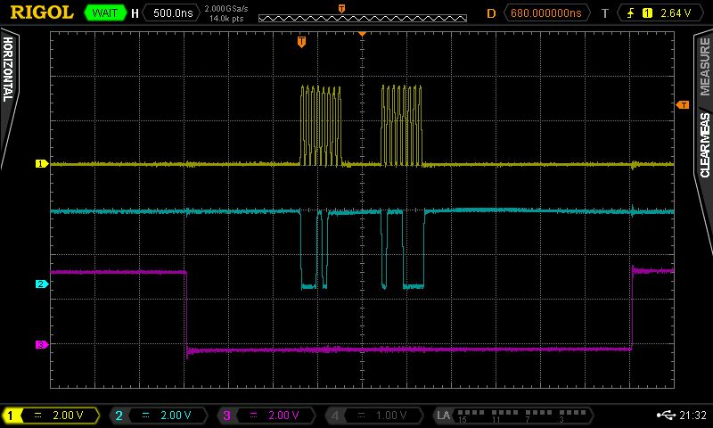
As you can clearly see in the picture above, there is about 1.25 µs of time difference from the falling edge of LE to the first rising edge of the CLOCK. There is even more time –about 2.5 µs– between the last falling edge of the CLOCK and the rising edge of the LE signal. A total 3.75 µs of time is wasted since there is no data being sent or received during these time slots. This wastefulness is per LE cycle. When there are 10 LE cycles, it scales up to 37.5 µs, which is a significant amount to waste for an RF synthesizer that aims to achieve a total lock-time of 100 µs. Therefore, we modified the soft LE as shown in the code snippet below:
With code shown above, the SPI waveforms look like the following:
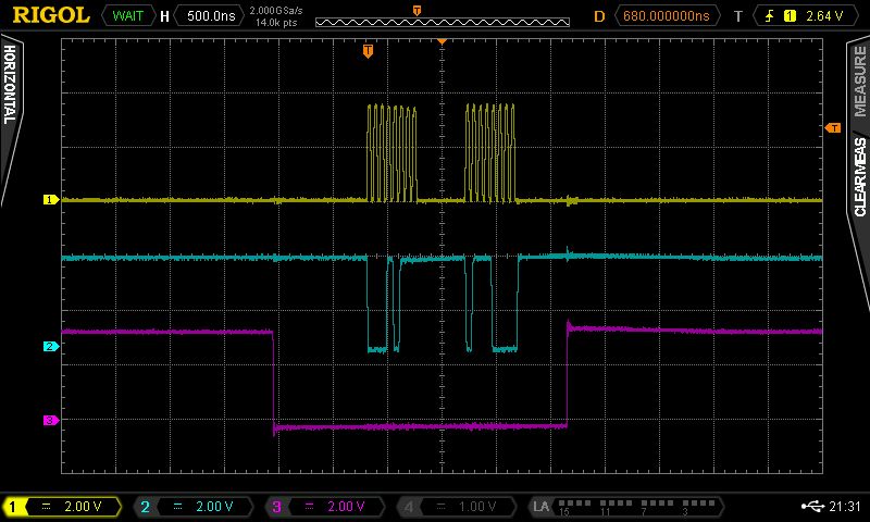
As you can see in Figure 3, by directly manipulating the port pins, we were able to save more than 2.5 µs of time per LE cycle.
Inclusion of Buffers, FRAM and Temp Sensor:
We further improved upon Arduino Due by bringing an FRAM, many buffers and a temperature sensor on-board. We needed some form of storage to keep the calibration values. An EEPROM is the usual choice, but we selected FRAM for its longer durability and faster access times. RF circuits are extremely vulnerable to MCU noise. We did not take any risks. We buffered and filtered each and every control line.