Project update 11 of 27
HyperRAM controller for USB analysis
by Mike WOne of LUNA’s core features is the ability to perform protocol analysis of USB 2.0 low-speed, full-speed, and high-speed. For most target devices, LUNA can endlessly stream the capture directly to a host PC over its own high-speed port. However, for high-bandwidth target devices that can’t be streamed in real-time, LUNA has 8 MiB of memory on board to buffer captured data before sending it upstream.
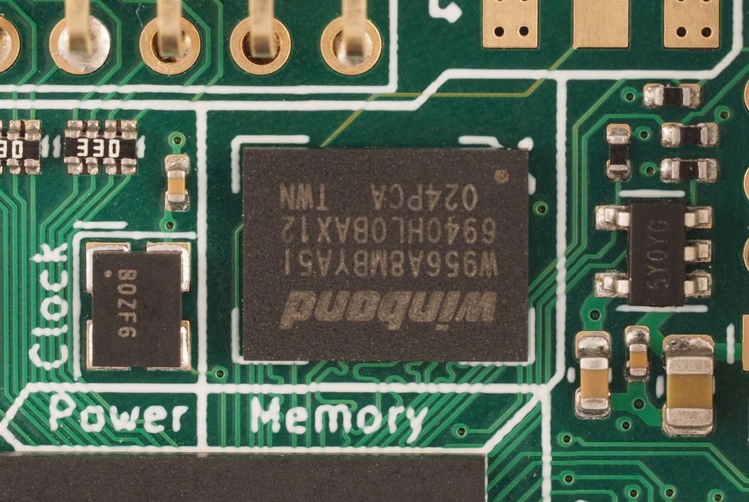
On LUNA we’re using HyperRAM, a type of pseudo-static RAM, which is capable of achieving relatively high speeds while being much simpler to work with than DRAM as it handles refreshing of the memory array by itself. Recently we’ve been working on our Amaranth gateware that interfaces with the RAM, implementing support for memory-space reads/writes and speeding it up so that we can keep up with USB analysis.
Speed
For USB analysis, we need to be able to stream data through the RAM at a nominal 480 Mbit/s but, since the ram is half-duplex, we need to hit at least double that. We also need to allow for some overhead for the RAM protocol. In our controller we run the RAM at 120 MHz DDR for a nominal rate of 1920 Mbit/s, which gives us plenty of margin to keep up with high-speed USB.
The Lattice ECP5 FPGA used on LUNA has a nifty feature in the I/O cells called gearing, which serializes/deserializes data to allow the I/O pin to run at a high speed without requiring the FPGA fabric to match it. For our HyperRAM controller we use the IDDRX1 and ODDRX1 cells, which take a 2-bit signal and read from/write to I/O pin at double the speed.
Timing challenges
A challenging part of interfacing with HyperRAM is the wide range of data-valid timing. The datasheet specifies that the data lines can be valid anywhere between 1 ns and 7 ns after a clock transition, and become invalid anywhere between 0.5 ns and 5.5 ns after the next clock transition. Running at 120 MHz the time between clock edges is only 4 ns, so this means that there is no fixed window in which to sample! The diagram below shows some examples of how the data-valid window could be shifted relative to the clock:
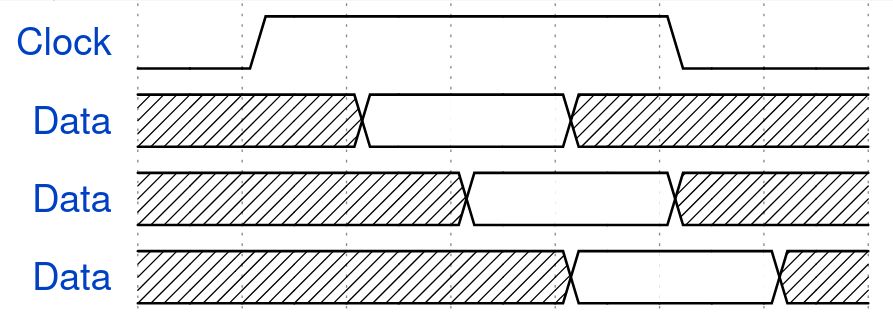
We solve this by using the ECP5’s I/O delays to shift the data-valid window and align it with a clock edge. These delays are variable so we can adjust them during operation to find the range of values that result in successful memory reads, then pick the value in the middle for the ideal sampling point.
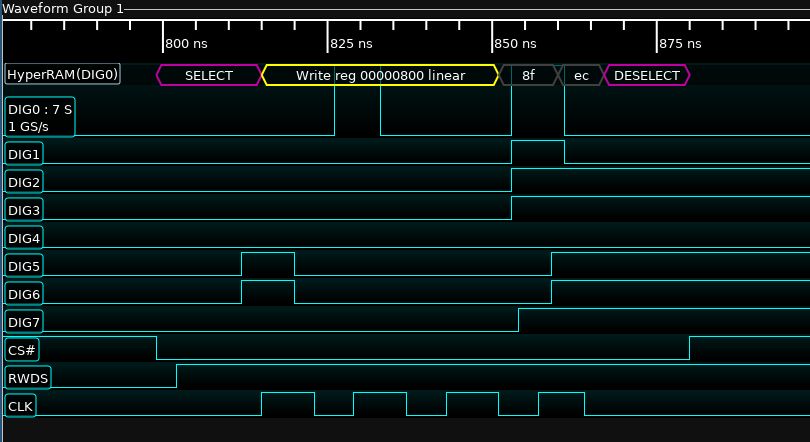
Debug tooling
For projects like this, it’s important to have good tools for debugging! As part of this work we wrote a HyperRAM decoder for glscopeclient, an open source frontend for oscilloscopes. This makes it easy to interpret waveform captures from the real hardware, and verify that everything is working as expected. The decoder has been merged upstream, so it’ll be available with any recent glscopeclient install.