Project update 3 of 14
A Deep Dive Into Our "Test Prints" Feature
by Alfredo BoniniSo far we’ve talked quite superficially about the features of Lite3DP Gen 2. Today we’ll focus on one of the new features we’ve introduced for Gen 2, test prints. Join us as we dive into the technical details of this ingenious tool!
Test Prints
The mSLA 3D printing process is actually quite simple. First, images in PNG format of the sections of the part to be printed are generated with Slicer software (Chitubox, Lychee, Prusa Slicer, Voxeldance Tango, etc.), and then stored in a folder on the microSD card. The printing consists of showing these images in an orderly manner, turning on the UV light for the duration of the exposure time, raising the platform to peel off the piece from the film of the resin vat, lowering it to the same extent as it was raised minus the thickness of the layer, and wait for the rest time, if any.
When starting to operate a new machine, it is natural to start with simpler procedures and add complexity as you gain confidence. In the case of 3D printers, a test print gives the user the assurance that part of the work has already been done, all that remains is to focus on the material to be used. In the case of mSLA 3D printers, the material is resin and its use will be defined by some variables such as exposure times and layer thickness.
To improve the appearance of the interface, we use images as templates. (Unlike the Lite3DP S1, where we only use primitive geometric shapes). These images in PNG format are converted to an array and included in the Arduino code that is uploaded to the ESP32 microcontroller. Once the firmware is uploaded with these arrays, they are stored in the ESP32, so it is not necessary to use a micro SD card to display them. This same method is valid for any image, even to transform the sections of a 3D model into arrays. However, 40 images are needed for each millimeter of part to be printed. If we wanted to store all that number of images on the ESP32, the memory would be insufficient, in addition to the process being infinitely tedious.
But what would happen if the 3D model had the same section for several millimeters? It would be a matter of programming to display the same image in all the corresponding layers. That’s precisely what we did, for each of the three layer thicknesses available in Gen 2: 0.025, 0.05 and 0.1 mm.
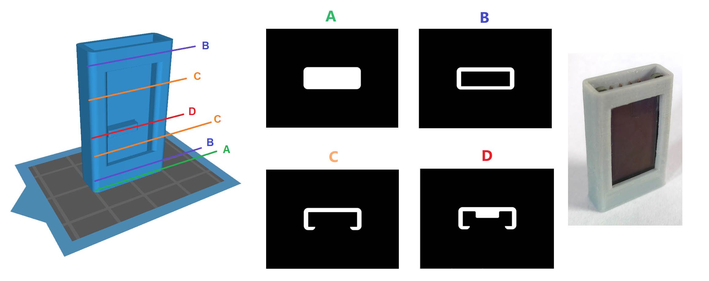
The OLED cover uses this method and is included as a test print in the Dev Kit. Optionally, you can print this last part of your Lite3DP Gen 2, on your own Gen 2! In the following image you can see that only four sections are used to make the entire 35 mm high part:
Reviewing the code, for each section of the part, it is similar to the following:
for (int l = 21; l <= 282; l++) {
  delay(RestTime);
  int16_t rc10 = png.openFLASH((uint8_t *)BB, sizeof(BB), PNGDraw);
  if (rc10 == PNG_SUCCESS) {
    tft.startWrite();
    rc10 = png.decode(NULL, 0);
    tft.endWrite();
  }
  ledcWrite(ledChannel, PWMUV);
  delay(expotime * 1000);
  ledcWrite(ledChannel, 0);
  TFT_BLACKscreen();
  pausing();
  movasc(hUp, delayLiftSpeed);
  delay(topdelay);
  movdesc(hDown, delayRetractSpeed);
  OLEDprint();
  number ++;
}
Which, in natural language, would be something like…
Repeat the following instructions for layers 21 to 282:
- Rest time after retract.
- Display the array-image of the current section on the screen.
- Turn on the UV LED, and keep it on for the exposure time.
- Turn off the UV LED.
- Black screen.
- Allow printing to pause, if the button is pressed.
- Raise the platform upwards in an amount equal to lift distance.
- Small delay to stabilize movement.
- Lower the platform in an amount equal to lift distance minus layer thickness.
- Show the printing progress on the OLEDscreen.
- Increase the number equivalent to the section by one unit (layer height of 25 um), to have a record of the height reached.
However, we didn’t stick with just one method for making test prints. What if we could make a printed part solely from a simple geometric shape that varies according to one or more equations, without using any image?
For the “touch pencil”, the second test print included in Gen 2 with a touchscreen display, a smooth circle (geometric primitive) is used as a section, always with the same center. The radius of the circle changes with the sections, reducing linearly at its body and quadratically at the tip.
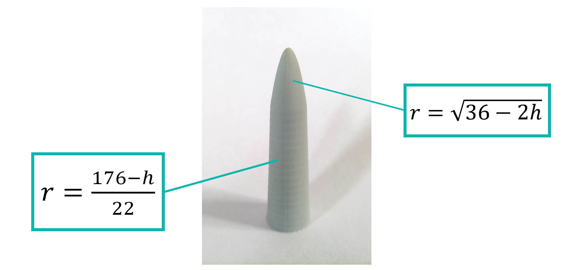
Where r is the radius and h is the height (h = l*layer thickness).
This is the code that prints the linear part at a layer thickness of 0.100 mm:
for (int l = 6; l <= 1760; l++) {
  tft.fillScreen(TFT_BLACK);
  delay(RestTime);
  radius = (176 - l * 0.025) / 2.5245;
  tft.fillSmoothCircle(240, 160, radius, TFT_WHITE, TFT_BLACK);
  ledcWrite(ledChannel, PWMUV);
  delay(expotime * 1000);
  ledcWrite(ledChannel, 0);
  TFT_BLACKscreen();
  pausing();
  printprogress();
  movasc(hUp, delayLiftSpeed);
  delay(topdelay);
  movdesc(hDown, delayRetractSpeed);
  number ++;
}
Which, in natural language, would be something like…
Repeat the following instructions for layers 6 to 1760:
- Black screen.
- Rest time after retract.
- Definition of the radius based on the current layer.
- Draw a white circle on a black background, in the center of the screen and with radius according to the previous calculation.
- Turn on UV LED during exposure time.
- Turn off UV LED.
- Black screen.
- Allow printing to pause, if the button is pressed.
- Show the printing progress on the screen.
- Raise the platform upwards in an amount equal to lift distance.
- Lower the platform in an amount equal to lift distance minus layer thickness.
- Increase the number equivalent to the section by one unit (layer height of 25 um), to have a record of the height reached.
We encourage you to hack on the firmware, which is now available in our GitHub repository so you can develop your own test prints. If you have any questions, we are at your service.
The Print Jobs You Requested
Below are a few parts that we printed, at your request, using Lite3DP Gen 2. This call is still open, so please contact us using the Ask a question link on our campaign page, and we will be happy to print your parts and include their pictures in future updates!
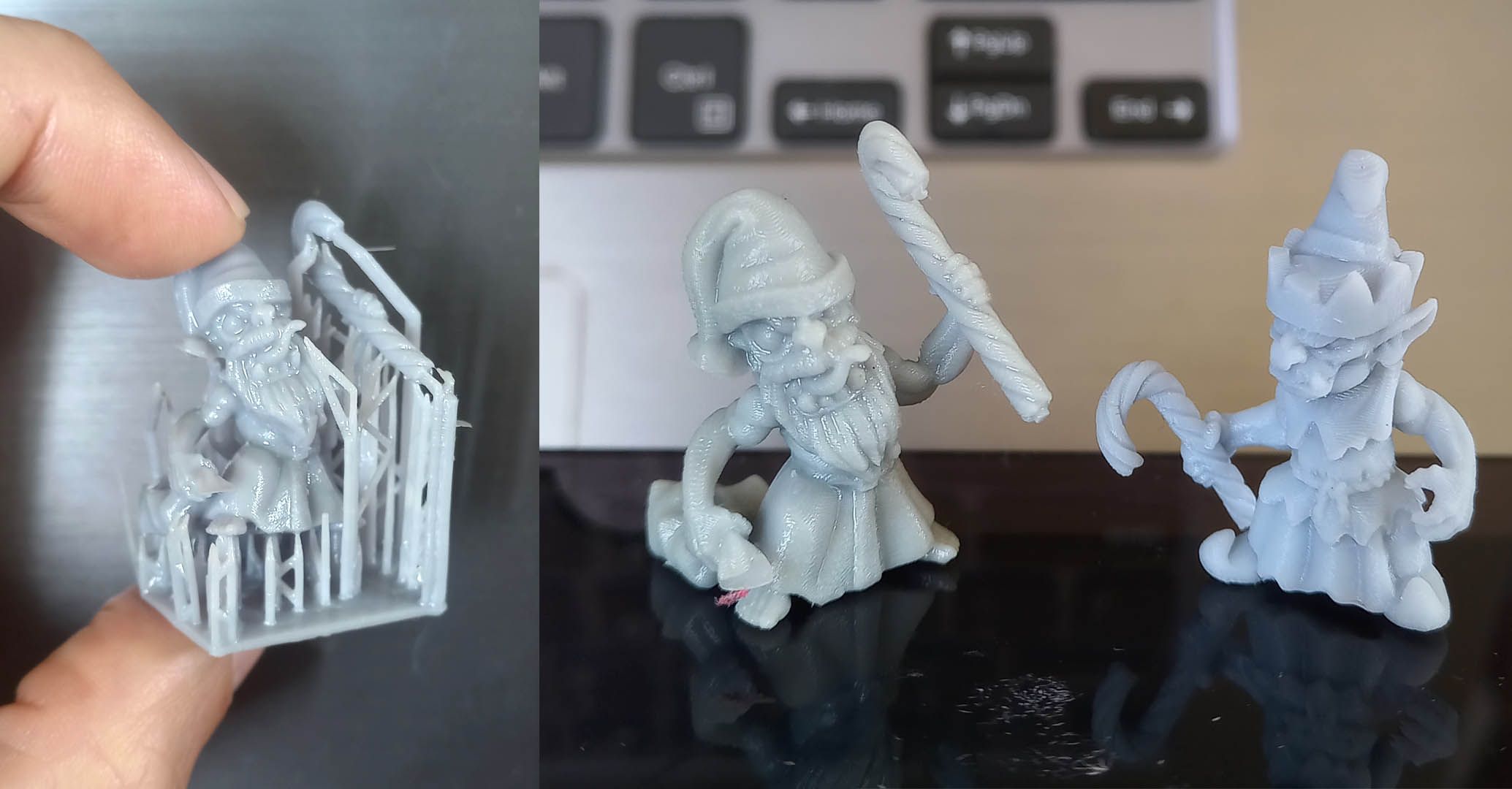
Christmas Goblins by Duncan Shadow. Suggested by Filippo B.
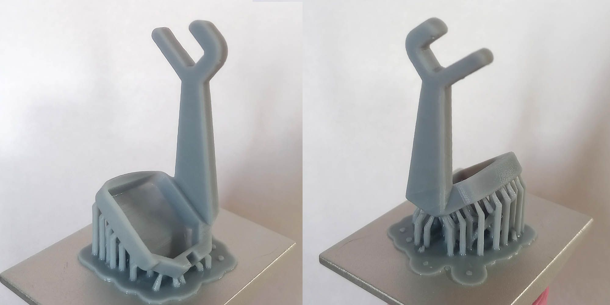
Component of the EYEDAK vrAse A2 open-source VR glasses. Suggested by Philip C.
All of the parts above were printed with standard, water-washable resin, with a layer height of 100 um.
Have a Great Week!
We hope you’ve enjoyed this update. We’ll be back in a few days with more information about the Lite3DP Gen 2!