Project update 7 of 8
How to Design a Card Module
by Longan LabIn our previous post, we talked about how to create or modify the firmware of a card module. In this post, we will introduce the process by which you can design your own. (For reference, here is a list of all currently available card modules.)
Required Skills
You should be familiar with:
- Eagle CAD software
- Basic electronic circuits
Download the Template
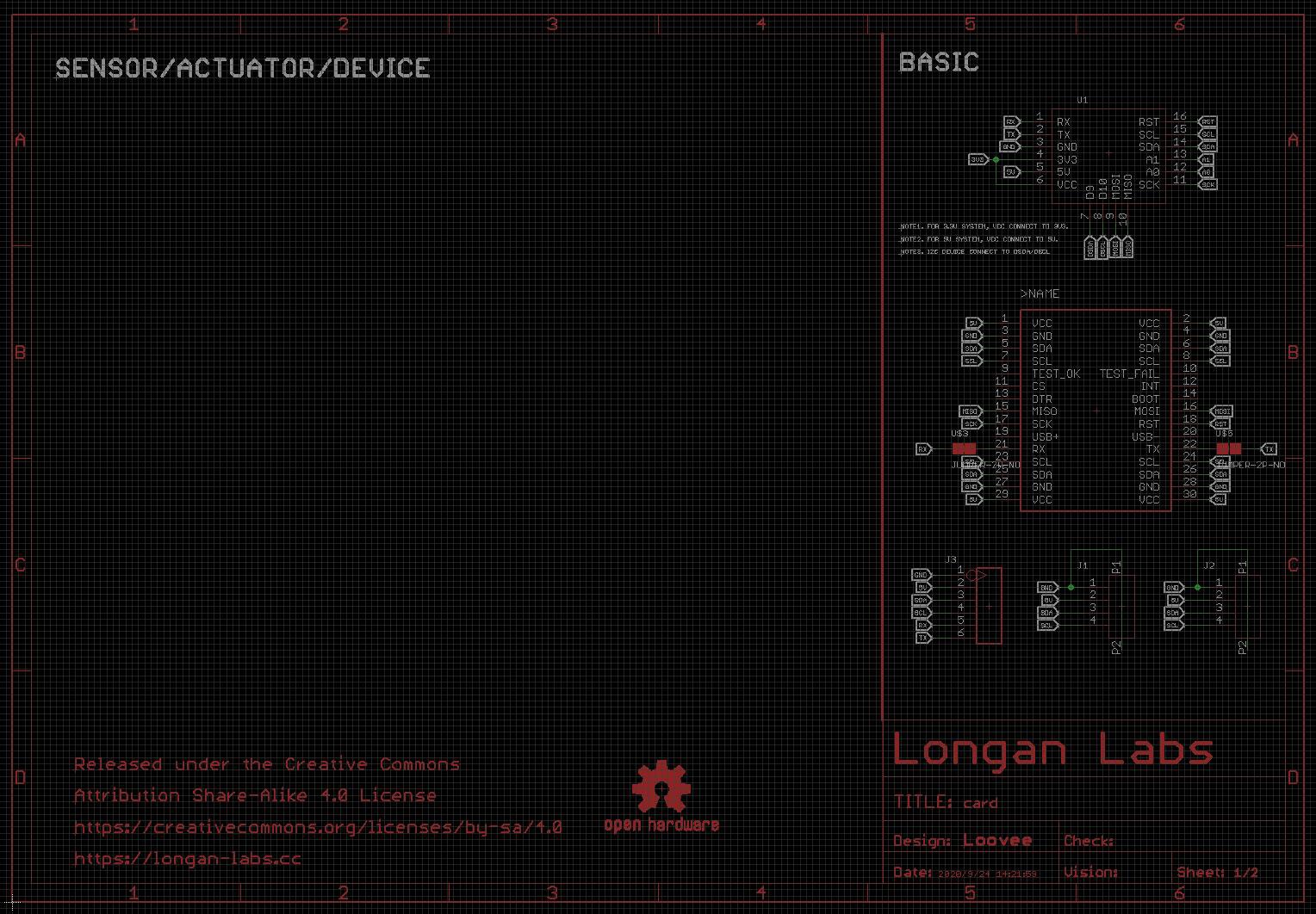
We provide a downloadable Eagle template to help you get up and running quickly. If you open the template, you’ll see that we’ve completed the core of the schematic for you. All you need to do is add your components to the blank area on the left-hand side.
Design Your Module
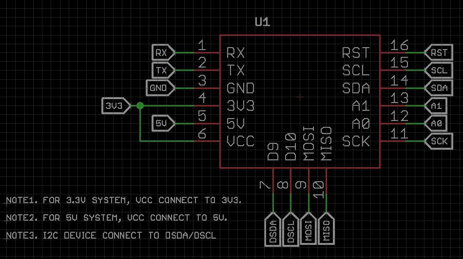
In the schematic diagram, you will see a device called U1, which is the smallest system module of a single-chip microcomputer. It offers the following interfaces:
- 1x I²C
- 1x UART
- 1x SPI
- 2x Analog input
- 2x Digital I/O
If you are using the I²C interface, you should connect the I²C of the device to DSDA/DSCL. The same goes for others interfaces, such as UART/SPI devices and analog input devices. You should also pay attention to the power supply. If the device you are using is 3.3 V, you need to connect the VCC of U1 to 3V3 of U1. Otherwise, you can connect it to 5V.
An Example
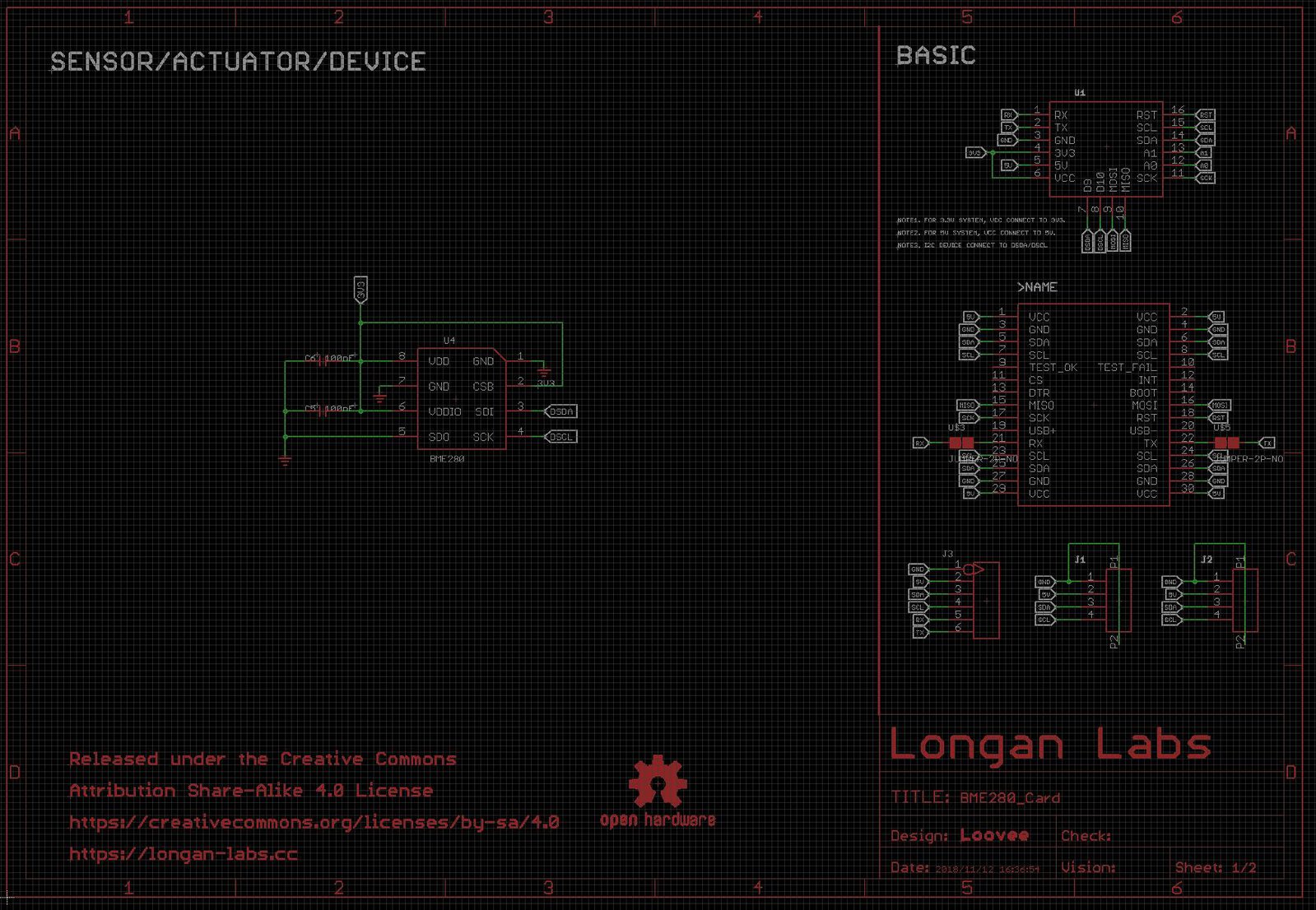
To demonstrate how easy it is to design a card module, let’s take a look at the BME280 Card, which is a temperature, humidity, and pressure sensor.
If you compare this to the template, you can see that all we did was add a BME280 chip and made a few simple connections. For a closer look, you can download the Eagle file for the BME280 Card.


