Project update 6 of 11
Example SwarmDrive Firmware for BLDC Motor Commutation: Part I
by Majodi PloegmakersI decided to dig into the SwarmDrive example code to explain some important concepts. The code, available on GitHub, is my attempt to translate the basic theory behind BLDC motors into easy to understand code. I am sure many things could be done differently and/or more efficiently. But my practical engineering goal here is to have a basic and easy to understand starting point. In this first part we will have a look at setting up the code and how to obtain motor characteristics needed for the commutation later on.
Context
To get some context, the main function (app_main()) starts with setting up the console thread (initConsole()). This starts a separate thread, pinned to a separate core of the ESP32, that handles UI functionality while running the motor commutation code. It is able to react to commands and set parameters while executing commutation code.
Next, the "Motor Config" structure is set up with some initial values before the actual motor class is instantiated on its own separate thread and core. At this point the constructor code can run.
Initialization
The constructor of the ns_svpwm motor class first will initialize the Rotational Position Sensor. Then it will set up a lookup table for the Space Vector angle values. The rest of the code will use this lookup table (LUT) instead of calculating angle vector duty cycle values over and over again.
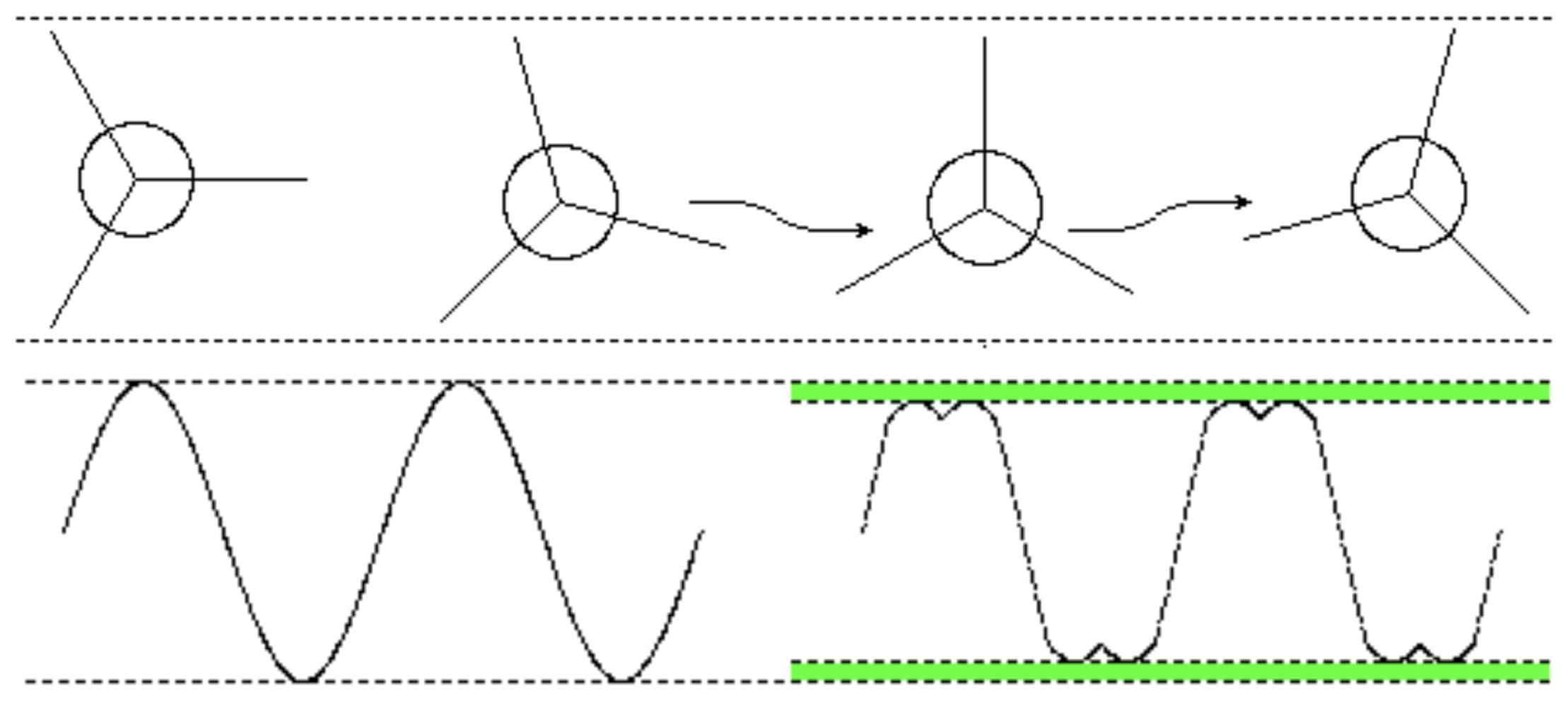
The nice thing about SV commutation is it can utilize full rail-to-rail power. The wave form produces 15% more power than a normal sine wave. This is because of something I call the "wobble effect." The X-axis is not fixed, but moves up and down to get maximum rail-to-rail power. There is a lot of information available on the internet about this, both mathematical and more practical. For me, one of the best resources was Dave Wilson’s explanation in “Teaching Old Motors New Tricks – Part 3” (starting at minute 24 into the video). I also found this more mathematical explanation useful.
After this table is created (which takes just little time), the ESP32 MCPWM module is initialized. This sets up the ESP32 to produce a symmetric PWM wave form which is typical for SV motor commutation. Now we can gather motor characteristics like stepping angle and direction. This is important information about the currently “unknown” motor connected to SwarmDrive. The information will be needed for the actual commutation later on. The main goal now is finding out how the SV values, stored in the LUT, translate to actual physical movement of the motor. This is done with determineSignalRotationAngleR().
Determining Direction
When the motor is homed, the RPS sensor should read zero. However, this will almost never be the case. Imagine an analog clock where "home" is the noon position. When we move one single LUT index step, the rotor (clock hand) should move a tiny distance positively or negatively (depending on how the motor’s coils are physically connected). However, one step can be too small to produce any physical movement. So, in the first loop, the rotor is moved a number of tiny steps, in total 1/3 of a signal rotation (120 degrees). This means that 1/3 of the LUT values will be sent (duty cycle values from the LUT are fixed).
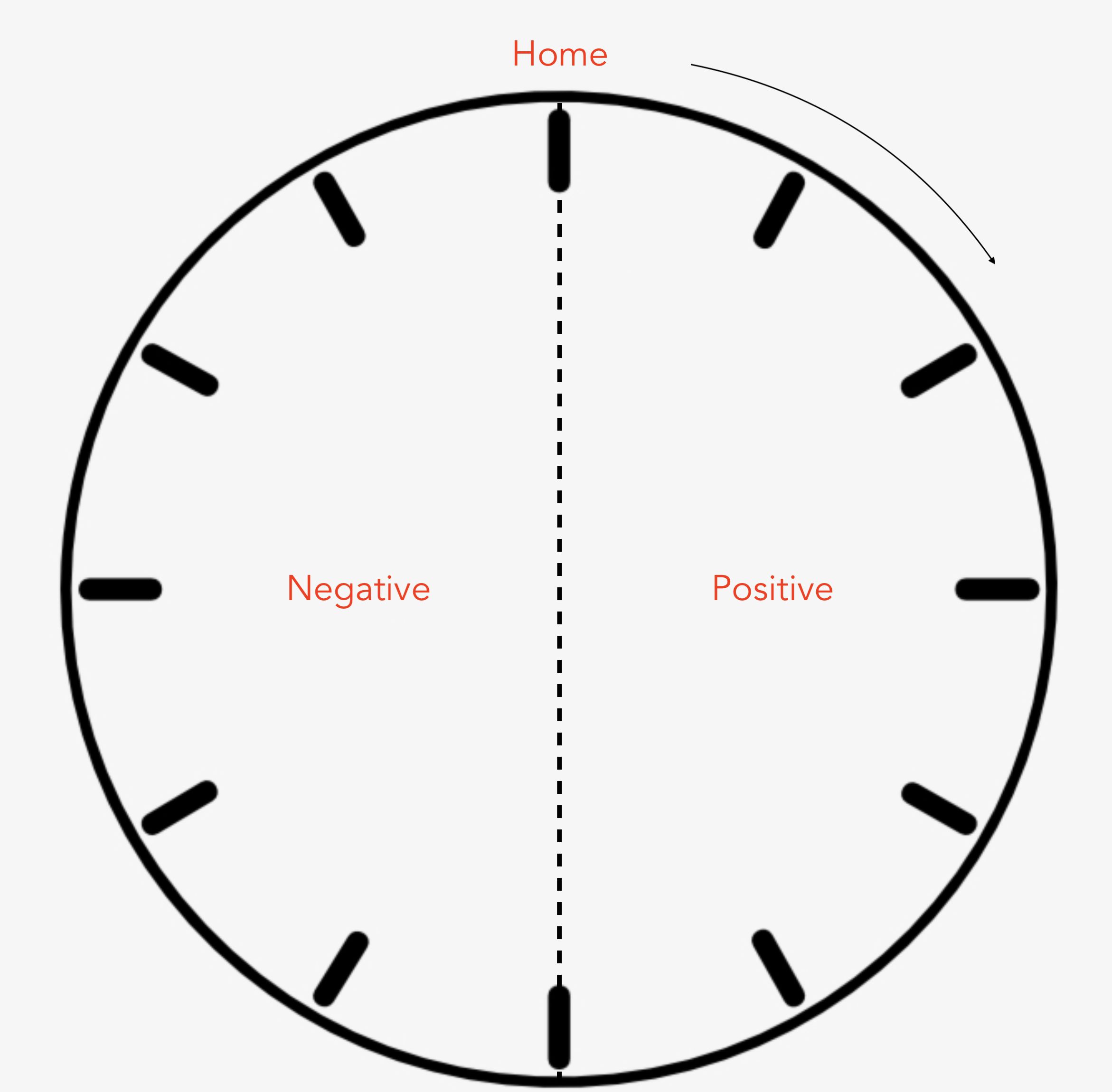
Now the angle position should have moved positively (clockwise) or negatively (counter-clockwise). In other words, if we call 6 o’clock to 12 o’clock the negative area and noon to 6 o’clock the positive area, we can determine if the rotor went from positive to negative or the other way around. This determines the built-in direction of the motor (again, based on how it is wired). When needed, we can change this by using reverseMotor(). This will allow us to consistently predict direction, no matter how the coils are connected.
Determining Angle Ratio
We now home the rotor again and position it at the beginning of positive area (one second after noon in our clock analogy). If we landed on the negative side after the homing command, we will step in the positive direction until we find the noon crossover point.
This time, we’ll take larger steps (1/4 of a full signal cycle or 90 degrees each step) and measure the delta angle using the RPS. So, we don’t use micro steps in index order of the LUT as we did before, but in stead we skip steps and jump to quarter values of the LUT for each step. We repeat this for a complete physical turn. Now we can count the number of 90-degree steps and the minimum delta. Note that, one thing that can go wrong (depending on the motor used) is that the motor is still not moving positively for the first few steps. These steps (until the motor finally moves into the right direction) will be ignored.
So, now we know how many quarter steps it takes to make a full physical turn. That means we know the number of pole pairs of the motor and what physical movement one small signal step should produce. This can be used to micro step the motor into a desired position. However, to determine ‘goal’ angles when spinning the motor with a certain torque value, we’ll also need a way to translate signal steps to physical angles.
How? We’ll discuss that in our next update covering commutation.
Until next time, Majodi