Project update 4 of 13
Exploring the Spatial Features of Sound Waves
by Andy WilsonFor this update, let’s take a closer look at the MEMS microphone array on PICO DSP and how it can be configured to change the microphone pickup pattern.
How does the microphone array work?
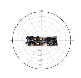
All MEMS microphones have an omnidirectional pickup response, which means they respond equally to sounds coming from any direction.
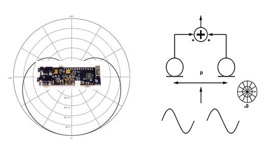
Multiple microphones, in our case two, can be configured into an array to form a directional response or a beam pattern. If the signals from the two microphones are summed or added, a broadside array is formed and signals from the side are attenuated.
Spatial sampling and aliasing
Aliasing is well known in cases where we digitize an analog signal in time domain. If we sample at a slower rate than twice the highest frequency (i.e., the Nyquist/Shannon theorem), we cannot mathematically reconstruct the original signal from the sampled signal without ambiguity. More exactly, we can reconstruct the signal, but we have no way of telling if it is the same as the original. A microphone array has the same effect on sound waves travelling in space. From time domain sampling theory, we know a minimum of two samples is needed to perfectly reconstruct a waveform. The same concept applies to microphone arrays. Therefore, to avoid direction-finding ambiguity we must have:
- f < v/2d
where v is the velocity of sound or the speed of sound in air (343 m/sec), f is the frequency, and d is the distance between the microphones. The maximum frequency this array can handle without direction-finding ambiguity is v/(2d), which is the spatial aliasing frequency. On PICO DSP, the distance between the microphones is 14.29mm, giving us a spatial aliasing frequency of 12 kHz.
Microphone spacing and DSP delay
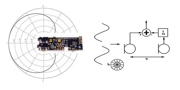
If the signal from one of the microphones is summed with an inverted and delayed signal from the other microphone, an "endfire differential array" is formed. The cardiod pick-up pattern can be modified by changing either the distance between the microphones or the DSP sample delay time.
Matching the distance between microphones with the DSP delay is critical to the performance of the beamforming array. In many audio applications, the choice of delay time is quantized by the sampling rate (fs). If a DSP’s delay is quantized by the period of a single sample then, when fs = 48 kHz, the minimum delay is 21 μs. At 20° C, the speed of sound in air is 34 3m/sec, or, a sound wave travels about 7 mm in 21 μs. This relationship can be shown as:
- d = n x v/fs
where d is the distance between the microphones, n is the number of samples of DSP delay, v is the velocity or speed of sound in air (343m/sec), and fs is the sampling rate or sampling frequency.
On PICO DSP, the distance d between the microphones is calculated to match a delay time of two samples for a sampling rate of 48 kHz, or a delay time of one sample for a sample rate of 24 kHz:
d = n x v/fs, when fs is 48 kHz and n=2, = 14.29 mm d = n x v/fs, when fs is 24 kHz and n=1, = 14.29 mm
How does PICO DSP compare to other microphone array development boards
During development, when we were looking at other boards with microphone arrays, it was difficult to find documentation about the design parameters needed for the array processing, such as how far apart the microphones are spaced on the PCB. Some other boards were not open source so often this information was not included in any of the hardware documentation.
For example, on the ReSpeaker Pi Hat, which is open source and has an available PCB design file, we had a look at the Eagle board file and found the distance between the microphones, d, is 59.69 mm. This gives us a spatial aliasing frequency (v/dx2) of 2873 Hz. This frequency is lower than the frequency of the human speech band at around 3 kHz to 3.4 kHz so, in theory, there will be ambiguity in direction finding for frequencies above the spatial aliasing frequency.
The distance d of 59.69 mm on this board also doesn’t match up to any of the most commonly used sampling rates or delay times for digital signal processing (it’s d = n x v/fs again!): for 8n samples and a sampling frequency (fs) of 44.1 kHz, the microphone spacing should be 62.22 mm, or, for a sampling frequency of 48kHz, it should be 57.16 mm.
Summary
Microphone arrays make it possible to explore the spatial features of a sound wave. Microphone beamforming is a complex topic, but, we’ve had a quick look at how the microphone array on PICO DSP was designed to match sampling frequencies of 48kHz and 24kHz and to raise the alisaing frequency to around 12kHz, well above the speech frequency band. If you’re interested in reading more about the microphone array, it was designed according to the theory and parameters outlined in this application note, which outlines some of the trade offs, advantages, and disadvantages of different beamforming configurations.
For the next update, we’ll have a closer look at the audio codec and see how you can use some of the additional functionality written for the audio driver.