Project update 7 of 21
Hidden Features of the μArt
Hiya!
In this update we’ll talk about the hardware of the μArt again. I’m sure you know the important features of this adapter by now, but there are some other features that tend to just "fly under the radar". Features that are too insignificant to make it into a traditional feature list or that are not usually advertised or stressed. But hey, I thought I’ll talk about these too, as they show some new aspects of the product and give you some insights into the design process and the care that went into it.
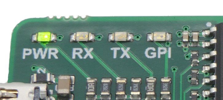
The power LED
"So what, a power LED?" - Well kind of. Actually it seems most isolated UART adapters don’t have a power LED, but that’s not the important thing here. What is interesting is not the presence of a power LED in the μArt, but how it works. With other products, the power LED is just strapped between the USB supply and its ground with a resistor, making it light up whenever you apply power to the USB side. Cool, except pretty useless, because with an isolated adapter it doesn’t really tell you anything. Even if it lights up, the UART side might still be powered down, or powered in reverse, or there could be some other fault. Point is, with other products, the PWR light does not actually tell you that the product is fully powered and is ready to transmit signals. The contrary is also true: just because the power LED is dark, it does not mean the product isn’t under voltage. If you ask me, these totally defeat the purpose of a power light.
For the μArt, I wanted the power LED to have meaning. When it lights up, it should say "ok, all systems are well powered, I’m transmitting signals, just make sure the data lines are connected too". And that’s exactly what it means in the μArt. The power light in the μArt is connected - strictly through the galvanic isolation of course - to the UART side too, and it does not light up until both sides’ power is applied and is correct. It is dark if the USB side is missing power. It is dark if the UART side is missing power. Or if the UART side has reverse voltage. Or if the isolation IC is faulty for any reason. The PWR light in the μArt actually has a meaning, letting you know the whole device is correctly powered. A big time saver when looking for problems.
High CTI for compact isolation
The isolation part in the μArt is the MAX14932BASE. This part sets an upper limit to the isolation voltage the product can withstand. For this component it is 443 Vrms indefinitely (or 2750 Vrms if you go with the marketing-fueled claims of other products that forget to mention this is only true for a few seconds). But blindly using an isolation IC does not automatically give you its highest possible isolation voltage. As a designer, you further have to take care to maintain two minimum distances: clearance and creepage. The former is easy, but creepage distance makes things a bit more interesting, because it usually needs to be a lot longer than the pin distance of the isolator IC, at least for its maximum isolation capability. (I could write a whole article about sizing these distances and what these are, and in fact others have done so already, if you’re interested let me just point you to a PDF here.)
Now, the usual way out is to introduce air gaps in the PCB (simple slots or cutouts under the isolator), which increases creepage distance to the distance around the slots. The slots, though, cannot be chosen arbitrarily. Regulations require them to have a minimum width of at least 1 mm. I also cannot place a single one of these in the μArt, otherwise the PCB would either fall into two pieces, or it would need to be 2-3 cm taller, with lots of empty space around the edges. So what people do in such a case is they introduce two parallel slots, slightly shorter but offset around the middle. It would look something like this:
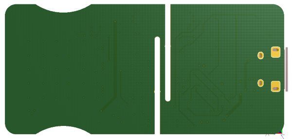
Let me stress explicitly that this is not how the PCB of the μArt looks. The above image is purely for demonstration. The problem with this approach is that the tiny part of PCB which remains between the two slots needs to be strong enough to hold the board together. In the case of the μArt it would have needed to be less than 0.9 mm wide… way too thin. You have to think about not just not breaking the board, but also preventing bending and flexing to avoid damaging the isolator and its solder joints, and this tiny piece of PCB between the slots would have been a perfect spring. If there wasn’t a plastic case, I’d call this planned obsolescence! Yet even with the case, I still don’t like it.
So if not this, there are only two solutions left. You can leave out the slots and just say your board has half the isolation capability of the IC inside it (which is not just a kind of waste, it would also mean the board would not be able to withstand mains AC anymore for an extended period of time). Or you can tweak the board’s material!
The surface material (in this case the solder mask) is key to creepage distance. Normal surface materials used for PCB manufacturing have a very low so-called Comparative Tracking Index (CTI), a CTI of around 200 V. A material with a higher CTI, however, is able to use lower creepage distances for the same isolation performance. And this is where the μArt is different. It doesn’t have any slots. Instead, the μArt uses a special solder mask with a CTI higher than 400 V, which means this safety distance can be a lot smaller compared to other products and yet achieve the same safety and insulation. The end effect is that the isolation capability of the isolator IC (443 Vrms) is fully utilized in the μArt despite its compactness, and this UART adapter thus withstands not only mains voltages, but withstands almost double that, and safely.
Reinforced connectors
Don’t we just love when a connector breaks off from the product? [rhetorical question]
I tried to make sure this won’t happen with the μArt. I’ve chosen a USB connector with four soldered through-hole side-wings, giving it the great strength of THT connectors.
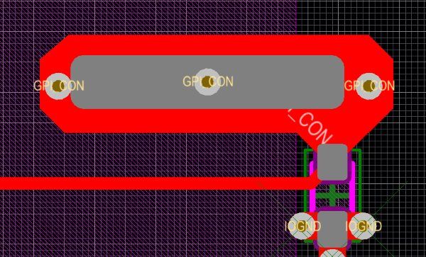
The 10-pin connector on the UART side is SMD, so to strengthen it, I enlarged the copper pads, making them stick stronger. In addition, I also use multiple vias in each of them to anchor down the pads across the whole thickness of the board, giving the pads a "semi-through-hole" structure. The picture below demonstrates the concept. The gray area in the middle is the usual/recommended pad layout that is covered with solder, the larger red area around it is the extended copper providing extra adhesion, and the three circles inside are the extra vias for even more strength. (To the right, below the pad you can also see the placement and routing of this pin’s ESD protection, but this is irrelevant to the topic at hand.)
The miscellaneous stuff
There are some really miscellaneous things too, so small that I am almost ashamed to write about them, so I’ll just list them quickly instead. The well-labeled board includes reminders on the back, the LEDs are matched in brightness (and PWR being slightly darker since it is usually on), the ergonomic edge-dents around the UART connector where you can grab the device steadily, the GPI LED allowing you to use the general purpose pin without host software, and the multi-function reprogrammable GPO pin, are all features small or not that will make your day easier and the μArt even better.