Project update 10 of 10
Out In the Wild & Expanding Possibilities
by Christopher GWe’re excited to report that all Hornet Nest Alarm Panel campaign orders have shipped and are now out in the wild! Supporters across the globe have begun installing their systems and the initial feedback has been overwhelmingly positive. It’s incredibly rewarding to see the project leave the prototyping bench and find its place in your homes and automation setups.

Expanding Outputs via I²C
Two key design principles of the Hornet Nest Alarm Panel are flexibility and expandability. Recently, one of our backers implemented output expansion using the onboard Qwiic (I²C) port and a PCF8574-based relay board.
By connecting a solid-state relay module with the DIP switches configured to address 0x24 (the first available Hornet Nest address), they successfully added eight additional relays. Here’s the snippet of code they added to the bottom of the default ESPHome configuration to support the external board:
pcf8574:
  - id: 'pcf8574_hub'
    address: 0x24
    pcf8575: false

switch:
  - platform: gpio
    name: "Relay1"
    pin:
      pcf8574: pcf8574_hub
      number: 7
      mode: OUTPUT
      inverted: true
  - platform: gpio
    name: "Relay2"
    pin:
      pcf8574: pcf8574_hub
      number: 6
      mode: OUTPUT
      inverted: true
  - platform: gpio
    name: "Relay3"
    pin:
      pcf8574: pcf8574_hub
      number: 5
      mode: OUTPUT
      inverted: true
  - platform: gpio
    name: "Relay4"
    pin:
      pcf8574: pcf8574_hub
      number: 4
      mode: OUTPUT
      inverted: true
  - platform: gpio
    name: "Relay5"
    pin:
      pcf8574: pcf8574_hub
      number: 3
      mode: OUTPUT
      inverted: true
  - platform: gpio
    name: "Relay6"
    pin:
      pcf8574: pcf8574_hub
      number: 2
      mode: OUTPUT
      inverted: true
  - platform: gpio
    name: "Relay7"
    pin:
      pcf8574: pcf8574_hub
      number: 1
      mode: OUTPUT
      inverted: true
  - platform: gpio
    name: "Relay8"
    pin:
      pcf8574: pcf8574_hub
      number: 0
      mode: OUTPUT
      inverted: true
We’ll include a couple of helpful photos below to show the board configuration and wiring for the Qwiic connector.
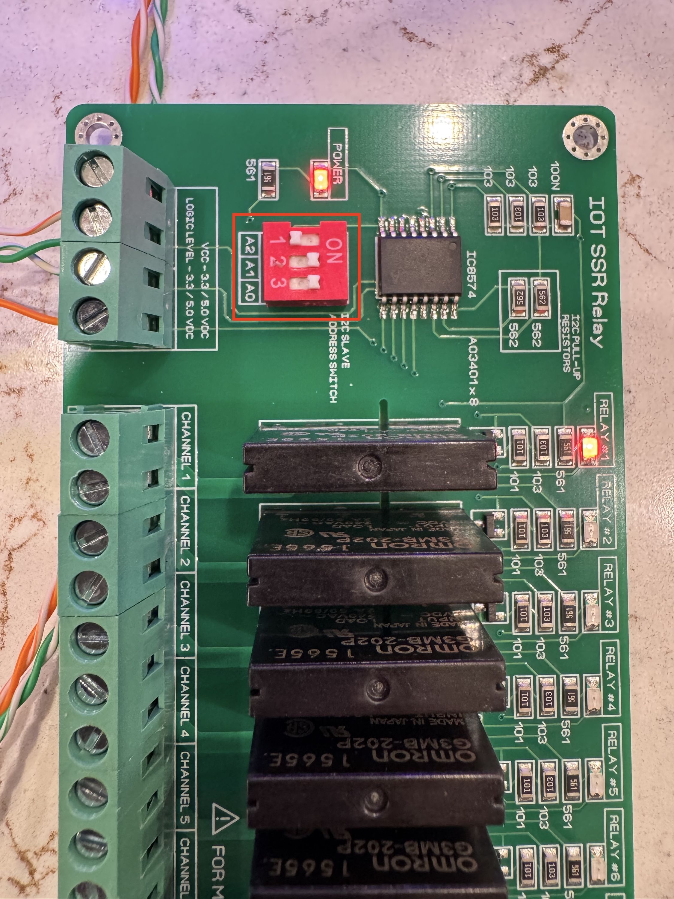
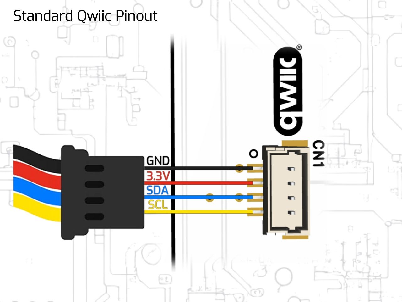
This kind of feedback and experimentation is exactly what we built the Hornet Nest for.
Wi-Fi Firmware Now Available
While the board was designed with Power-over-Ethernet (PoE) in mind for simplicity and reliability, we recognize that not all installations will support PoE. Based on user feedback, we’ve developed a Wi-Fi version of the firmware to allow the Hornet Nest to be used over Wi-Fi when desired.
To use the Wi-Fi version, follow these steps:
- Load the factory Wi-Fi firmware onto the wESP32 using a programming module.
- Connect to the
hornet_nestWi-Fi SSID and select your network.
NOTE:
The captive portal may not launch automatically. You can manually navigate to http://192.168.4.1/ to complete the setup.
- Once the board is detected by ESPHome, click Take Control.
- Allow the board to download, compile, and install the full firmware.
- Once complete, add the device to Home Assistant.
Everything is open source and fully documented in our GitHub repository: Hornet Nest Alarm Panel on GitHub
Thank You
We want to sincerely thank every one of you who backed this campaign and helped turn the Hornet Nest Alarm Panel from a personal project into a fully realized product. Your feedback continues to shape future improvements and we’re committed to supporting your installations with new features, expanded documentation, and ongoing firmware refinements.
If you have feedback, success stories, or questions, please reach out. We’re listening and we’re excited for what’s ahead.