Project update 8 of 15
Turning CANFDuino into an OBDII Monitor & Data Logger
by daniel kOBDII, or “on-board diagnostics,” is a standard connection and communications protocol required by the EPA since 1996. Starting with all vehicles produced after 2008, the CAN bus (ISO 15765) became the required communications hardware for OBDII. This means OBDII is a protocol that “sits on top of” CAN bus or, in other words, CAN bus enables OBDII.
OBDII is a transmit/respond type of protocol which uses a form of message multiplexing. This means in order to receive data over OBDII from your vehicle something (e.g., CANFDuino) needs to ask for it periodically. It also means that the same message ID is used to transmit and receive data with each message containing a sort of a “sub ID” for both the request and response message.
These sub ID’s are called parameter IDs (PIDs) in the OBDII standard. So the transmit and receive CAN ID’s, where the calls and responses are typically fixed (TX – 0x18DB33F1 or 0x7DF , RX – 0x18DAF10E or 0x7E8), the PIDs (data-byte three in the payload) specify what you want to monitor (vehicle speed, throttle position, RPM, etc.). A good list specifying the PIDs and, more importantly, all of the stuff you can monitor and log from your car can be found in this wikipedia entry on OBDII PIDs.
The libraries for CANFDuino contain OBDII classes (e.g., OBD2.h, OBD2.cpp) that make adding different PIDs (things you want to monitor and log) straightforward. You simply add a couple of lines of code for each new PID you want to monitor. For example, the line below can be added to your sketch (*.ino file). This code is a class constructor (C++) where you define the name, units, PID, size in bits, signed or unsigned number, current (real-time) data, slope in engineering units, offset in engineering units, the port number, and if you are interfacing with an extended ID vehicle or a standard ID vehicle (check forums for your vehicle or try both separately to see which works).
If you are having trouble adding a new PID to the example code provided, when in doubt do this: pick a PID from the example code to study first like "Speed" or "Throttle," then go to the PID wikipedia page linked above to see how we arrived at units, PID, slope, and offset, which you can copy/paste and modify. To add the PID, you’ll also need to do one more tweak to the OBDII.h file as shown below:
***** DEFINITIONS FOR OBD MESSAGES ON CAN PORT 0, see https://en.wikipedia.org/wiki/OBD-II_PIDs to add your own ***************/
//char _name[10], char _units[10], OBD_PID pid,  uint8_t OBD_PID_SIZE size, bool _signed, OBD_MODE_REQ mode, float32 slope, float32 offset, cAcquireCAN *, extended ID;

cOBDParameter OBD_Speed(      "Speed "        , " KPH"    ,  SPEED       , _8BITS,   false,   CURRENT,  1,      0,  &CanPort0, false);
Below is a code snippet showing the OBD2.h file PIDs, modify this if you wish to add a new PID.
/**
 *
 * This enum represents the Parameter ID field for a particular signal per the OBDII protocol
 */
enum OBD_PID
{

    ENGINE_LOAD  = 0x04,
    COOLANT_TEMP = 0x05,
    ENGINE_RPM   = 0x0C,
    SPEED        = 0x0D,
    ENGINE_IAT   = 0x0F,
    ENGINE_MAF   = 0x10,
    THROTTLE_POS = 0x11,
    FUEL_FLOW    = 0x5E
};
Getting Started
Ok, we have covered some background about OBDII and the provided code, the following tutorial will provide a quick method for getting OBDII vehicle communications and logging up and running with your CANFDuino.
Step One: Build & Test Your First Sketch
Before we get started, let’s make sure everything works. Follow our instructions for Installing the Library and First Sketch before trying anything with the vehicle.
Step Two: Wire up the OBDII port
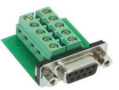
To connect the CANFDuino to your car, you’ll need to wire the unit to the OBDII port on your vehicle (must be 2008 or older to support CAN). You will need a vehicle interface cable (shown below) properly wired to CAN H and CAN L signals to the CANFDuino on port 0. This is simplified with a flying leads cable and a DB9 to screw terminal device, as shown below. Follow the hookup guide to connect CANH, CANL and GND
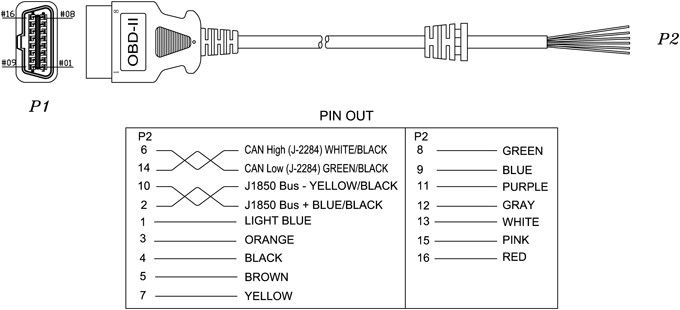
A note on OBDII-to-DB9 female cables: these type of cables have no flying leads on the end and instead go straight to DB9, which is great for mating to CANFDuino, right? Well, in theory, yes if you buy a cable that has CANH mapped to pin seven, CANL mapped to pin two, and GND to pin three. Many OBDII-to-DB9 F cables have CANH mapped to pin seven, CANL mapped to pin two and GND mapped to pin one. Please check the pinouts before you purchase a cable for OBDII or you may spend hours troubleshooting your setup.
Step Three: Format and Install an SD Card
The OBDII sample code logs PID values to CSV format on the SD card of CANFDuino (note: it will not function without the SD Card). This leverages the Arduino libraries for SD card support. As such, the card should be formatted to FAT16 or FAT32 per the reference library instructions. Once formatted, insert the SD card into the CANFDuino’s slot.
Step Four: Program it
Open the IDE and go to File->Examples->CANFDuino_OBD2Logger.ino. Note that, by default, this code uses the standard 11-bit IDs which have been tested on Mazda, Toyota, and GM vehicles, while the 29-bit ID has been tested on Honda and is probably less common than 11-bit. Make sure you have the proper board and port selected from Tools->Board->CANFDuino and Port->COMxx. Now click the upload button, which will verify and upload the code. Once completed, go to Tools->Serial Monitor and make sure the baud rate is 115K (for a cleaner static display, we suggest using PUTTY or Chrome Terminal for real-time monitoring (as we used in our CANTerm sketch example in the readme). Plug your OBDII cable into your car (located under the steering wheel, down very low) and start the vehicle.
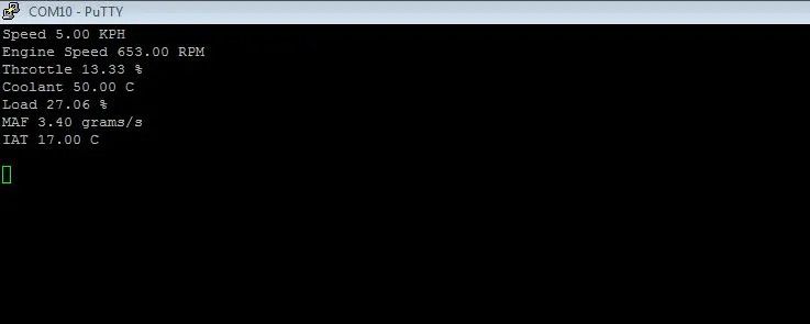
Step Five: Check Serial Monitor Messages
First, you will get a successful initialization message for the SD card. The board should be communicating with the car at this point. The easiest way to see if you are getting data is to watch the engine RPM message.
A successful monitoring from PuTTY will look something like this:
Monitoring from the Arduino terminal will look like this:
System Reset
Initializing SD card…card initialized.
Engine Speed 0.00 RPM
Throttle 0.00 %
Coolant -40.00 C
Speed 0.00 KPH
Load 0.00 %
MAF 0.00 grams/s
IAT -40.00 C
Engine Speed 862.50 RPM
Throttle 16.08 %
Coolant 59.00 C
Speed 0.00 KPH
Load 32.55 %
MAF 4.17 grams/s
IAT 25.00 C
Engine Speed 865.50 RPM
Throttle 16.08 %
Coolant 59.00 C
Speed 0.00 KPH
Load 32.55 %
MAF 4.10 grams/s
IAT 25.00 C
Step Six: Check Logged Data
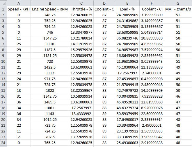
The OBDII data will be logged to a file on the SD card called “OBD2data.csv”. This format (comma-separated-values) is commonly accessible by applications like Excel, Google Sheets, Notepad, or any text viewer. Below is an example of a successful log. Note, if you plan to primarily use CANFDuino as a logger you may want to consider wiring the boot loader bypass jumper per the hookup guide.
Step Seven: Modify It!
Now you can add your own PIDs, change your logging rates, your displays, etc. Fork the repository and help the community further develop CANFDuino!
Thank you for your support, we wish you success!