Project update 28 of 76
Defeating electrical noise and preparing for EMC tests
Welcome to our monthly progress update! There is no shortage of news from this last month, so let’s go through them one by one!
Plastic case
We’ve already received samples of the bottom case parts, the buttons on the plastic case, and the top left and top right parts are well one their way. The following image is the top left part of the case with the sprue left on it.
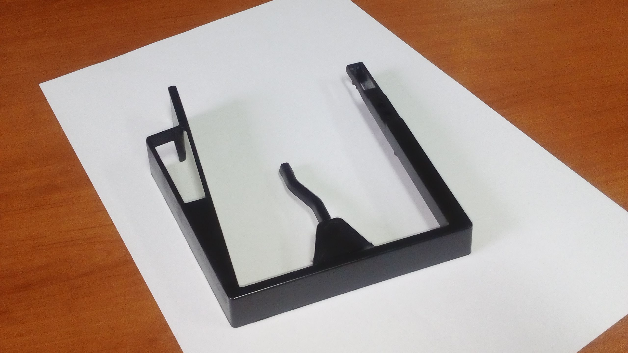
As it turns out, the ejector pins of the top left mold are unable to eject the part properly, so our contractor is in the process of adding an extra pin. We shall soon receive all the plastic parts of the case to evaluate them.
Palm rest
In the last update, we showed you the 3D printed prototypes of the palm rest. We also showed you foams of different types that could go into the palm rest. In the meantime, we’ve been thinking about using an alternative material to foam: wood.
Wood palm rests are considered to be the most premium solution. They’re nice to touch, pleasing to the eye, and last longer than foam palm rests. This is how our current palm rest prototype looks like.
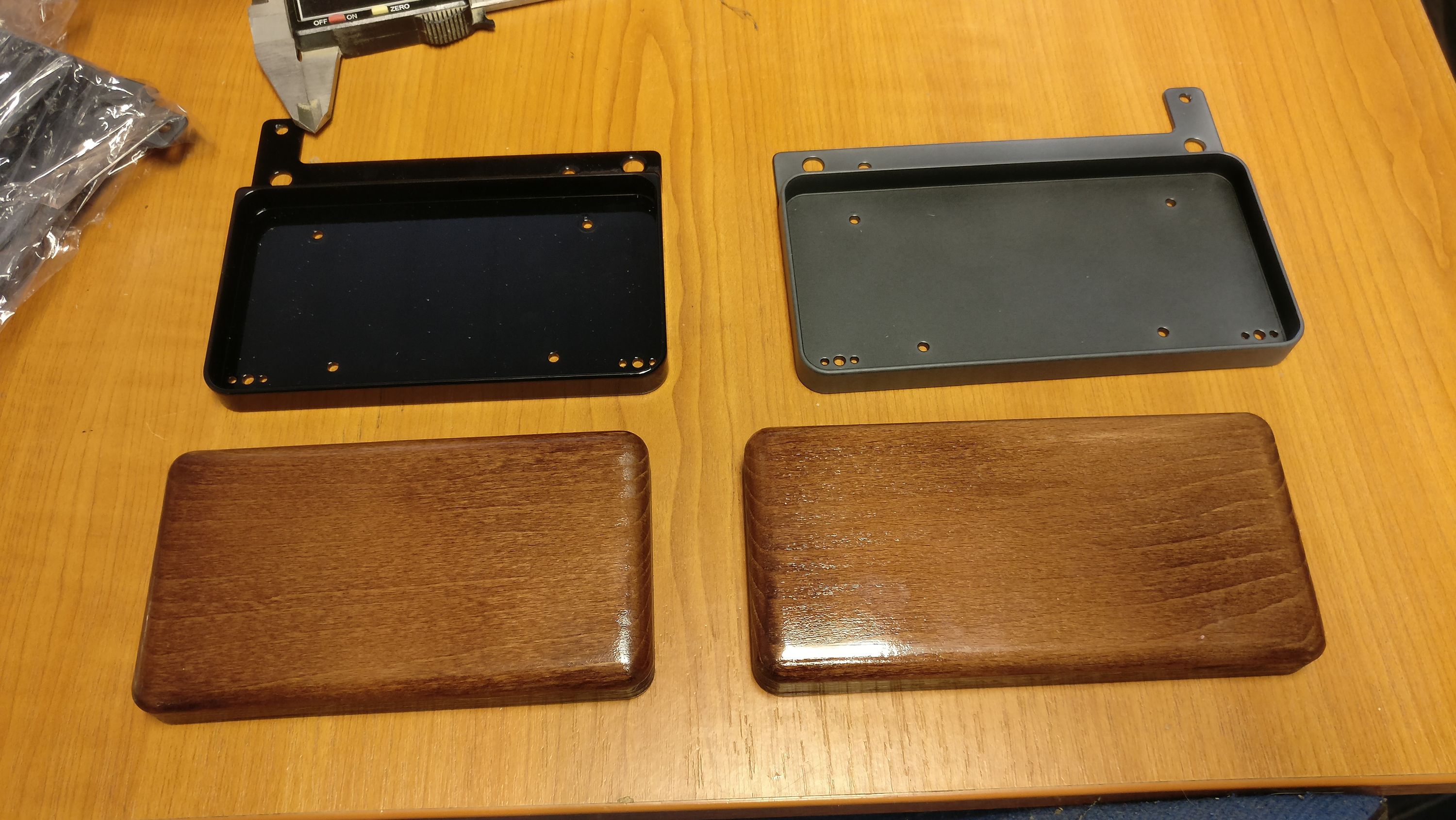
You can see the base plates of the palm rest on top. They’re milled out of solid aluminium, then anodized, and finally covered with lacquer. The left one was powder coated with glossy lacquer that did not change the black anodized color, and the right was covered with matte lacquer that changed the black anodized color quite a bit.
The current base plates feel extremely robust and look pretty nice, but to make them even more nicer, we’re thinking about powder coating them black instead of anodizing them. This would result in a solid, semi-gloss, black color. We’ll give it a try later.
As for the wood parts, beech wood was used which got slightly dyed, and then a glossy lacquer layer was applied. The gloss is too much, so we plan to settle with semi-gloss lacquer, and we’ll probably end up using a darker brown paint.
LED display
The last time we updated you, we mentioned that our LED display was having ghosting issues. This was caused by the white LEDs whose forward voltage was significantly higher than the other red and yellow LEDs.
We haven’t found a viable solution regarding the white LEDs, so we ended up using yellow LEDs for the icons. This makes the charlieplexed LED matrix use only red and yellow LEDs whose forward voltage is similar.
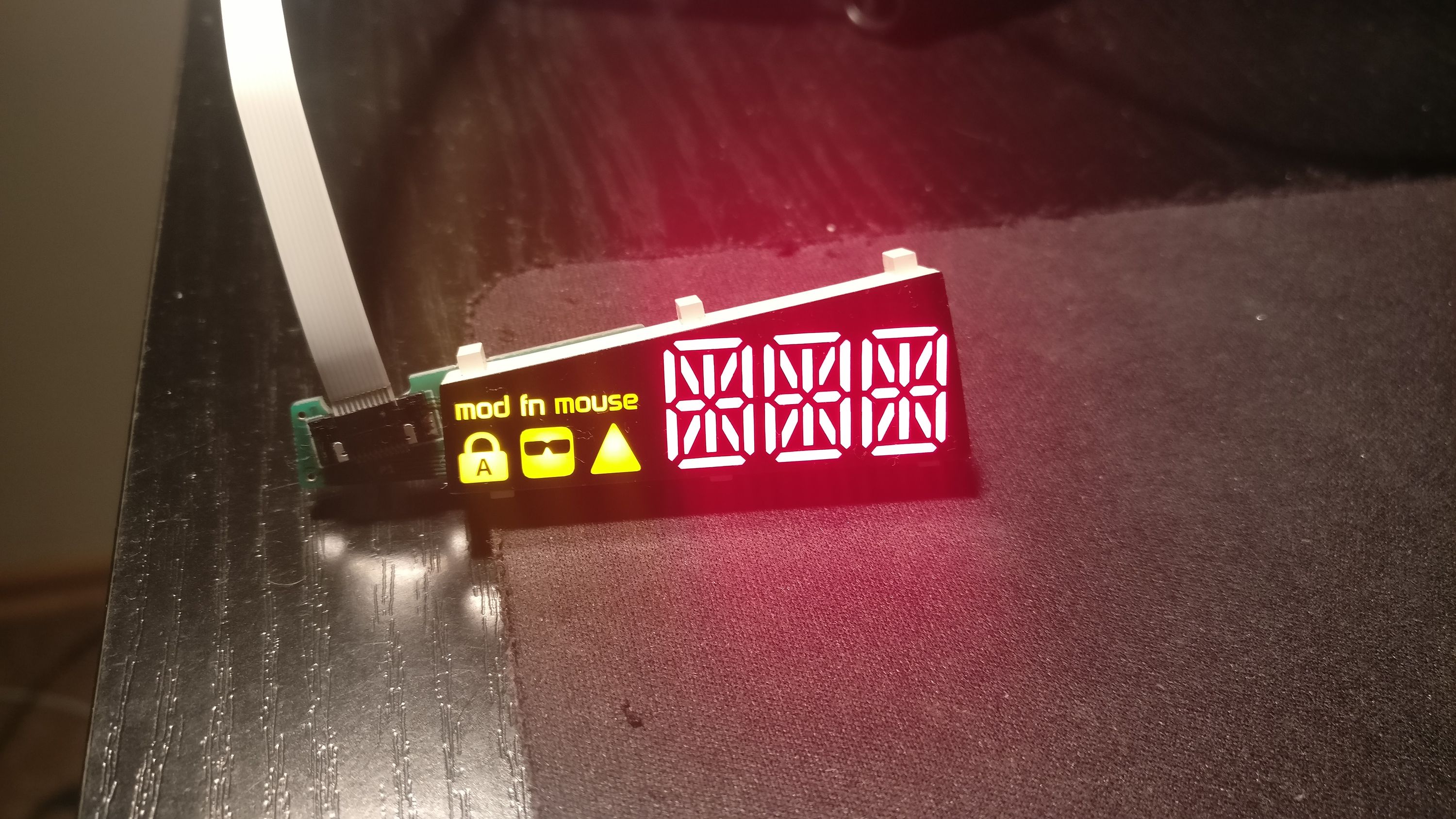
This simple fix has fully resolved the ghosting issue. Ghosts busted!
Bridge cable
One would think that the bridge cable is a no-brainer. After all, it’s just a simple spiral cable, so let’s just pick a random cable from any manufacturer and call it a day, right? As it turns out, that’s not exactly the case.
In the spirit of future-proofing the UHK for backlighting, I tested the bridge cable with all switch LEDs on to see whether it carries enough current to the LEDs.
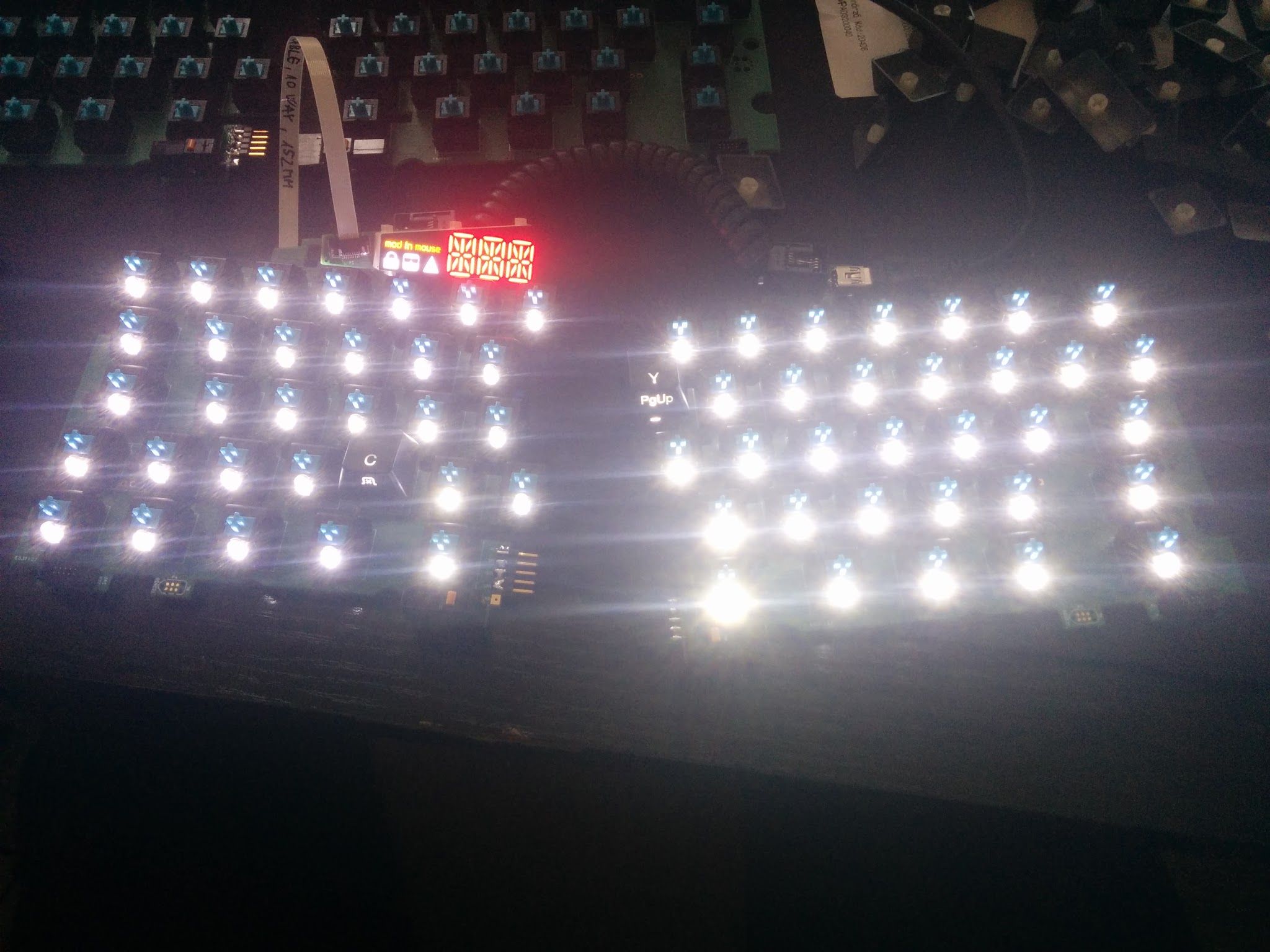
It’s clear that the right half is brighter than left. When connected via the board-to-board connector, the brightness level evened out the halves. It became apparent that the voltage drop of the bridge cable was very high.
I figured out that there are two factors that affect this issue, which are the diameter and the material of the wires inside of the cable. My bridge cable was made of copper-clad steel instead of pure copper, which conducts electricity much better. As for the diameter, the wires of my cable were extremely thin.
I then started contacting spiral cable manufacturers to learn more details and find the best option. As it turns out, 24-30 AWG diameter wires can be crimped to RJ jacks, so I asked for 24, 26, 38, and 30 AWG copper cable samples.
After testing them, I could confirm that the resistance of these cables was much lower than my original cables, and lighting was even across the keyboard halves with any of them. In order to minimize the voltage drop, I wanted to pick the thickest 24 AWG cable.
That’s when the manufacturer warned me that 24 AWG cables may not retain their shape after stretching them moderately, which was an issue I was able to confirm. I figured that it’s the plastic exterior of these cables that provide the flexibility. There was too much copper in thicker cables, which made them not retain their shape after flexing. After testing the samples, I figured that 28 AWG and 30 AWG retained their shape well. So I picked the thicker 28 AWG one, and this will be our final cable.
Lesson of the story: not all cables are created equal, and the devil is in the details!
Electrical issues
The UHK will have to pass EMC tests so that we can stick FCC and CE logos on the back, allowing for worldwide distribution. Being aware of this issue, I knew the time had come to send one of our prototypes to an electrical engineer to be investigated from an EMC standpoint.
Luckily, a friend of mine, Robi, just happens to be an electrical engineer. He’s not even a mediocre engineer, but a great one, and he was very willing to take a peek at our prototype.
After receiving the prototype, Robi was eager to get his hands dirty. The first thing he did is hook his prototype up to a scope. The results were somewhat worrying.
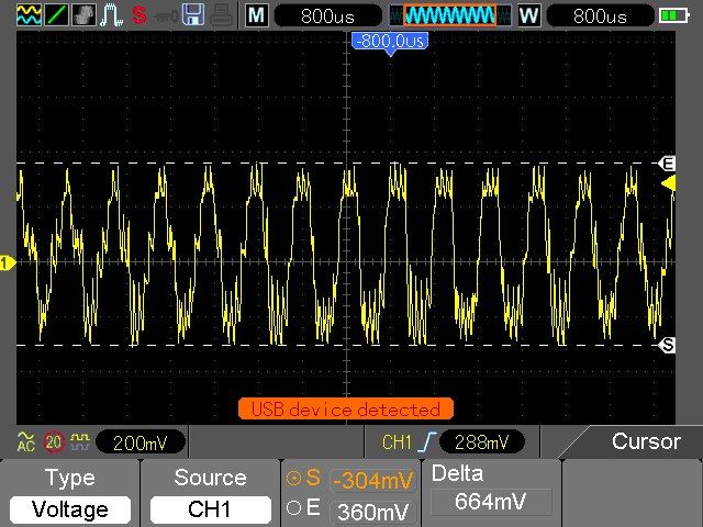
He told me that given this heavy electrical noise, there is not a fighting chance we’ll pass EMC tests.
About 5 minutes later he told me that he had bad news and good news. The good news is that he managed to solve the electrical noise issue.
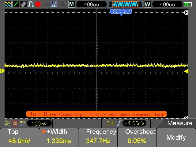
The bad news is that I wouldn’t like the solution.
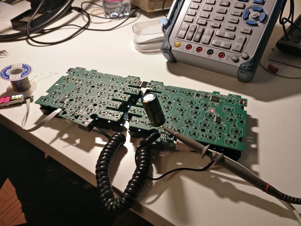
The elephant in the room is the monstrous electrolytic capacitor soldered onto the PCB. If you’re afraid that it won’t fit inside of the UHK case, you guessed it right!
Luckily, using multiple SMD ceramic capacitors can provide sufficiently high capacitance. Robi also suggested using a ferrite bead and some extra capacitors near to the USB connector to further reduce electrical noise issues.
Acoustic noise
In the previous update, I mentioned that our PCBs were emitting some audible noise which was proportional with the number of LEDs enabled. Robi also looked into this issue and the solution has several steps to it.
First, throwing more capacitors onto the PCB drastically reduces electrical noise, which in turn also reduces the piezoelectric effect responsible for the audible noise.
Second, the ceramic capacitors will be placed in a way that they won’t enforce each other’s vibrating effect.
Third, we’ll use higher value resistors for the R_EXT pins of the LED drivers because the current consumed by our latest prototype with all LEDs enabled is higher than the maximum current the USB connection can provide. Lower current draw will translate to lower noise, and given the logarithmic sensitivity of the human eye, the brightness difference will hardly be noticeable. LED lifespan will also benefit from this change.
We’re fairly confident that the above fixes will resolve every electronic issue. Our next PCB should be ready to pass EMC tests!
Bootloader
Santiago has been extremely busy with his work at NXP (now Qualcomm). So much so that he’s had hardly any time for us, but luckily, he managed to spend a whole weekend on the bootloader recently. Because of his efforts, the master bootloader is working! This means that it’s now possible to update the firmware on the right keyboard half via USB.
But that’s only half of the story. The other half involves implementing the proxy which will route the firmware of left keyboard half and add-on modules via the right keyboard half. If everything goes well, Santiago be able to allocate enough time to get this done soon.
Our new contributor

I briefly mentioned my friend, Róbert Csordás, above. He has been a huge help in solving the electrical issues of our design, so this is the part where we express our appreciation.
He hasn’t only helped with electrical issues, but also improved the firmware in a lot of ways. He implemented a QWERTY layout, then made the communication between the keyboard halves more robust.
Robi is already a full-time UHK user. His only wish is to receive a plastic case for his prototype, so that the bare solder joints of the PCB won’t scratch his desk. We’ll make sure to send him a final UHK with all the bells and whistles as soon as we can.
Thank you so much, Robi!
Project progress and schedule
Right now, the steel guides, the feet mold, the rubber mold, and the magnet counterparts are being manufactured.
The molds of the case, and the steel plate cutting tool are being adjusted to meet our manufacturing constraints. This is planned, but it will takes a little longer than expected.
The PCB is being redesigned as described above in order to minimize electronic and acoustic noise. It will be ready by the end of the upcoming week, and then we’ll put it through EMC tests in December. We should have the necessary certificates by that time. We’ll launch a prototype run for the PCBs in January and start our first full production batch in February.
By the time the boards get manufactured, we’ll have all the parts and packaging in our warehouse, ready to be assembled, and shipped.
We can assure you that everything happens according to the grand plan, but many things take longer than expected. We know how much you would love to have a UHK by the holidays, and we’re doing everything we can to deliver as soon as possible, but we can’t reasonably expect to ship sooner than February.
We’ll keep these updates coming with clockwork accuracy, so you’ll be aware of our progress at all time. Should you have any questions, we’re always here for you.
Thank you for your continued support, and we’ll talk to you again on 2016-12-15.