Project update 4 of 9
The Physics of Current Sensing
by Weston BraunI have received a number of questions about the mechanisms by which Little Bee operates, so I am going to devote this update to talking about the ways you can use Little Bee to sense current.
Field Sensing
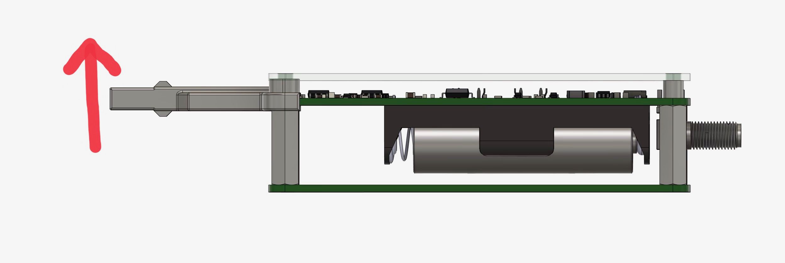
The Little Bee uses an Anisotropic Magnetoresistive (AMR) sensor to sense magnetic fields. These sensors use a thin film of a ferrous material that changes resistance when exposed to a magnetic field. This sensor is in the tip of the probe and senses the component of the magnetic field in the Z direction. Magnetic fields are a vector, so this means that the angle of the probe can impact the magnetic field reading. The sensor tip is 8.00 x 5.25 mm and the active part of the sensor is offset approximately 1.6 mm back from the end of the tip. The photo below shows the direction of the magnetic field for which Little Bee will provide a positive output voltage.
When Little Bee is first turned on, a current is passed through a small coil on the die of the sensor to align the magnetic domains in the sensing material. This is required to initialize the sensor and provide a known sensitivity and output polarity. The linear range of the sensor is +/- 6 gauss, which is about 20 times the strength of the earth’s magnetic field. With the current sensing attachment, the maximum current range of +/- 5 amps is mapped to the magnetic field range of +/- 6 gauss. A large magnetic field (or a large current with the current sensing attachment) will not damage the sensor, but it will disturb the alignment of the magnetic domains in the sensor, requiring the sensor to be reset. See the instructions on the GitHub repo for more details, but the sensor can be reset without impacting the zeroing of the probe by quickly tapping the reset/zero button.
Sensing Currents With Magnetic Fields
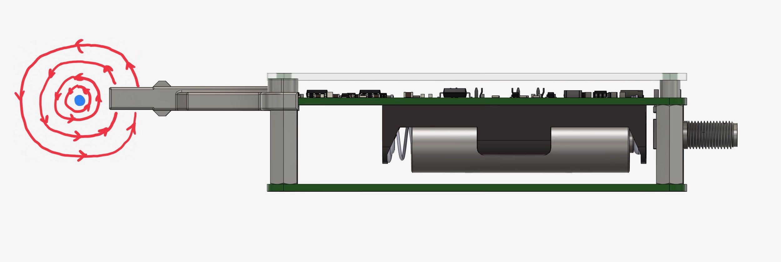
A wire with a current flowing through it generates a magnetic field that circles the wire at a right angle to the direction of current. This magnetic field is proportional to the current flowing through the wire. A PCB trace generates a similar field, but its not entirely circular. If the tip of Little Bee is placed on the wire with the correct orientation, the magnetic field can be sensed. The picture below shows the magnetic field lines (red) from a wire (blue) carrying current out of the page.
Assuming the wire is significantly longer than its diameter, the field strength drops off as the square of the distance to the wire. The field strength is sensitive to the return path of the current, such as which layer the current returns are on for a PCB. Given these factors, the amplitude of the current measured by directly measuring the field strength will not be that accurate, but is useful for debugging basic circuit functionality, finding short circuits, and taking waveform measurements. For optimal accuracy with field sensing you should calibrate the measurements with a wire or PCB trace of the same dimensions using a known current.
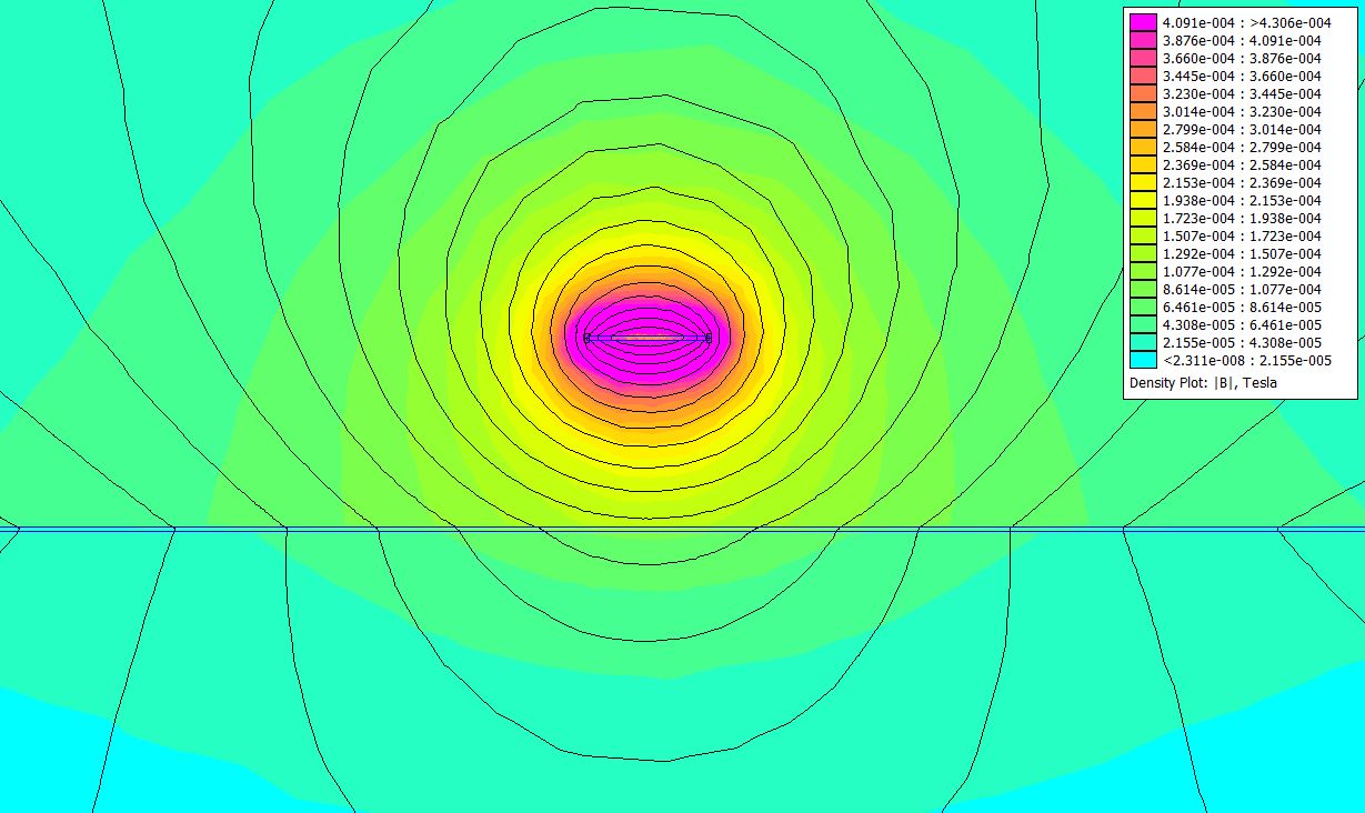
Using the free and open source magnetic modeling tool FEMM it is also possible to model the wire or PCB trace geometry and extract a gauss/amp value which can be translated to a volts/amp value using the known sensitivity of Little Bee. Below is an image of the magnetic field strength surrounding a 1 mm PCB trace carrying 1 amp that is 1.6 mm above a ground plane (FEMM plots field strength in tesla, 1 tesla = 1000 G ).
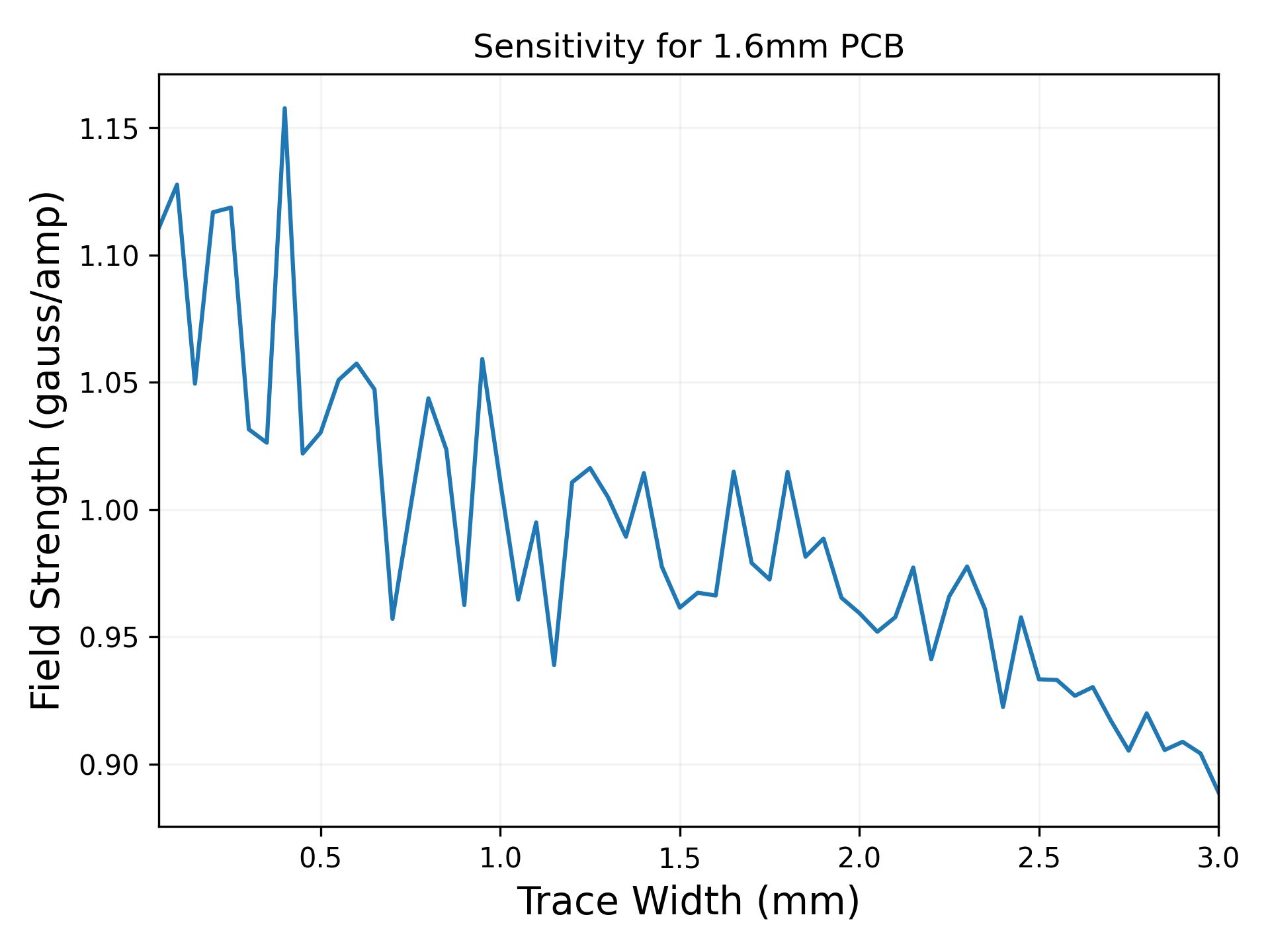
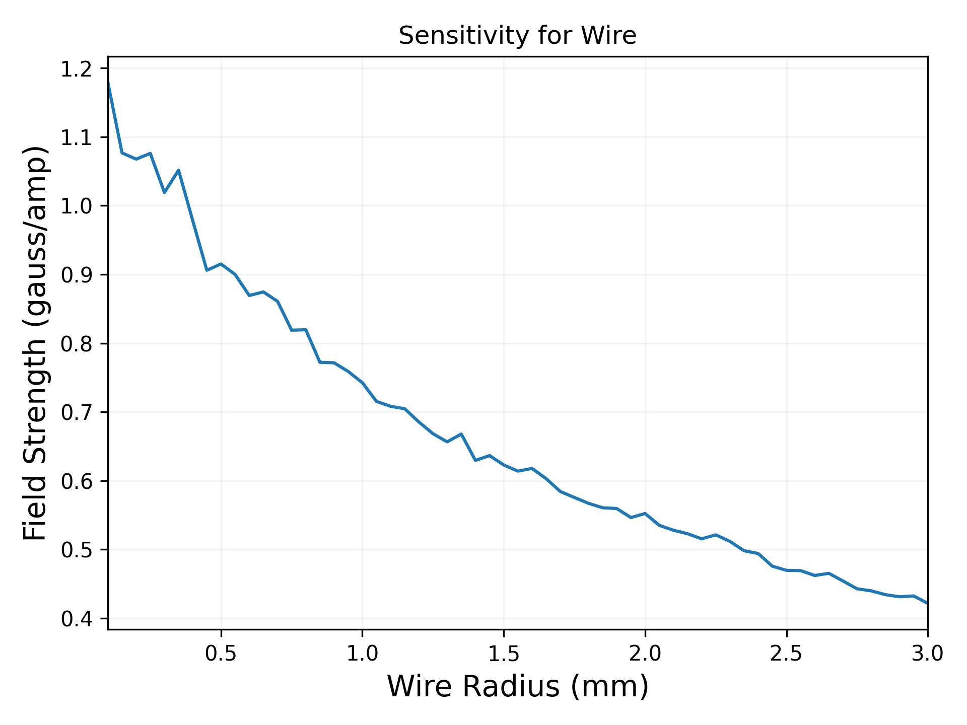
In the project repository there are some scrips that use the FEMM Ocatave scripting interface to calculate the field strength at the spot the sensor would be located for different PCB trace and wire geometries. Below are graphs of the field strength for a circular wire as a function of radius and for PCB traces above a ground plane on a 1.6 mm thick PCB as a function of width. In reality, these graphs should be monotonic, but the jagged edges are due to the meshing resolution in the model.
In the development of Little Bee a test structure PCB was fabricated, which allows for checking the accuracy of the magnetic modeling. From the below table, it can be seen that the readings are within a reasonable range.
| Trace Width | Measured Field Strength | Modeled Field Strength |
|---|---|---|
| 0.25 mm | 0.93 G | 1.1 G |
| 0.5 mm | 0.90 G | 1.03 G |
| 1 mm | 0.83 G | 1.0 G |
| 3 mm | 0.63 G | 0.89 G |
Current Sensing Attachment
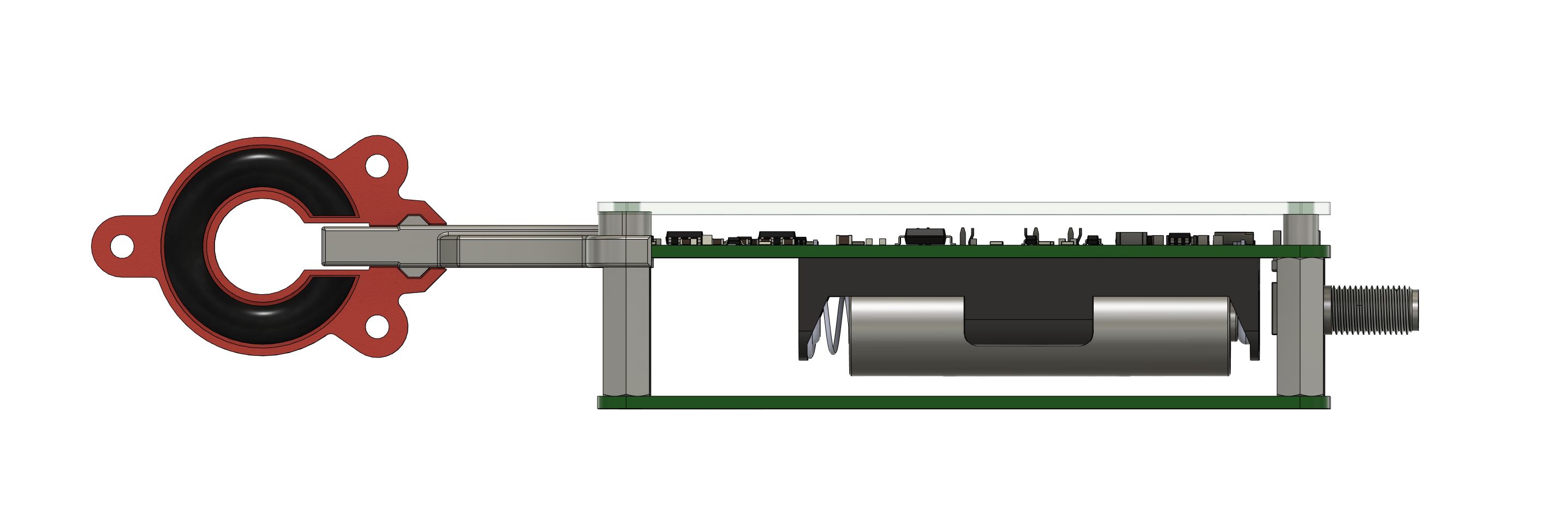
The current sensing attachment uses a ferrite ring with a gap to sense the current in a wire more accurately by concentrating the magnetic field, making the system relatively insensitive to the wire geometry. This attachment clips on to the end of the probe tip. The attachment can be slipped over the wire before being clipped on (max wire size of 4.2 mm) or threaded through the current sensing attachment (max wire size of 10 mm). Below we show a rendering of a cross section of the current sensing attachment as it is attached to the end of Little Bee. The housing of the current sensing attachment is red, the ferrite ring is black, and the tip itself is grey.
The current sensing attachment eliminates the impact of the shape of the wire but is still slightly sensitive to the location of the wire within the attachment. If the wire is directly against the probe tip the magnetic field at the sensor is higher and Little Bee can read up to a 20% higher current. For maximum accuracy, keep the wire from resting directly on probe tip while the current sensing attachment is in place.