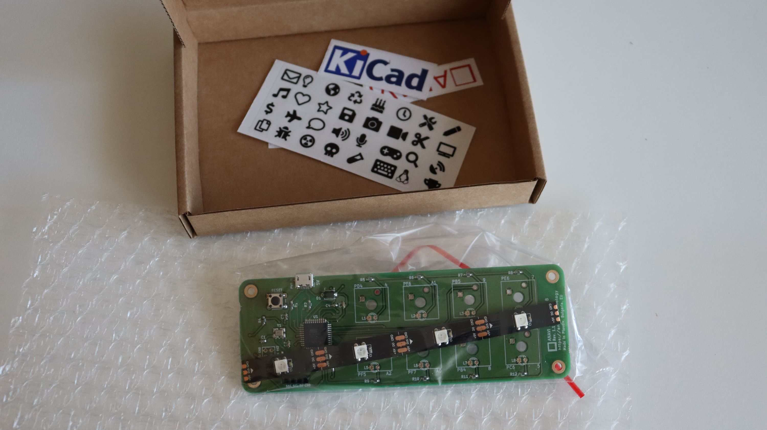
In a previous update we shared the exact steps how to assemble ANAVI Macro Pad 8 Developer Kit. Now let’s have a look at the Maker Kit.
The Maker Kit provides the printed circuit board (PCB) and an addressable LED strip. There are also some nice stickers. Other accessories have to be purchased separately. You can use any mechanical switches compatible with Cherry MX plate footprint and 3mm LEDs.
Furthermore with the Maker Kit you can perform a hot-swap upgrade of ANAVI Macro 8. It requires a very specific procedure which was explained in a previous article. If you have this in mind don’t solder anything and have a look at the other video tutorial.
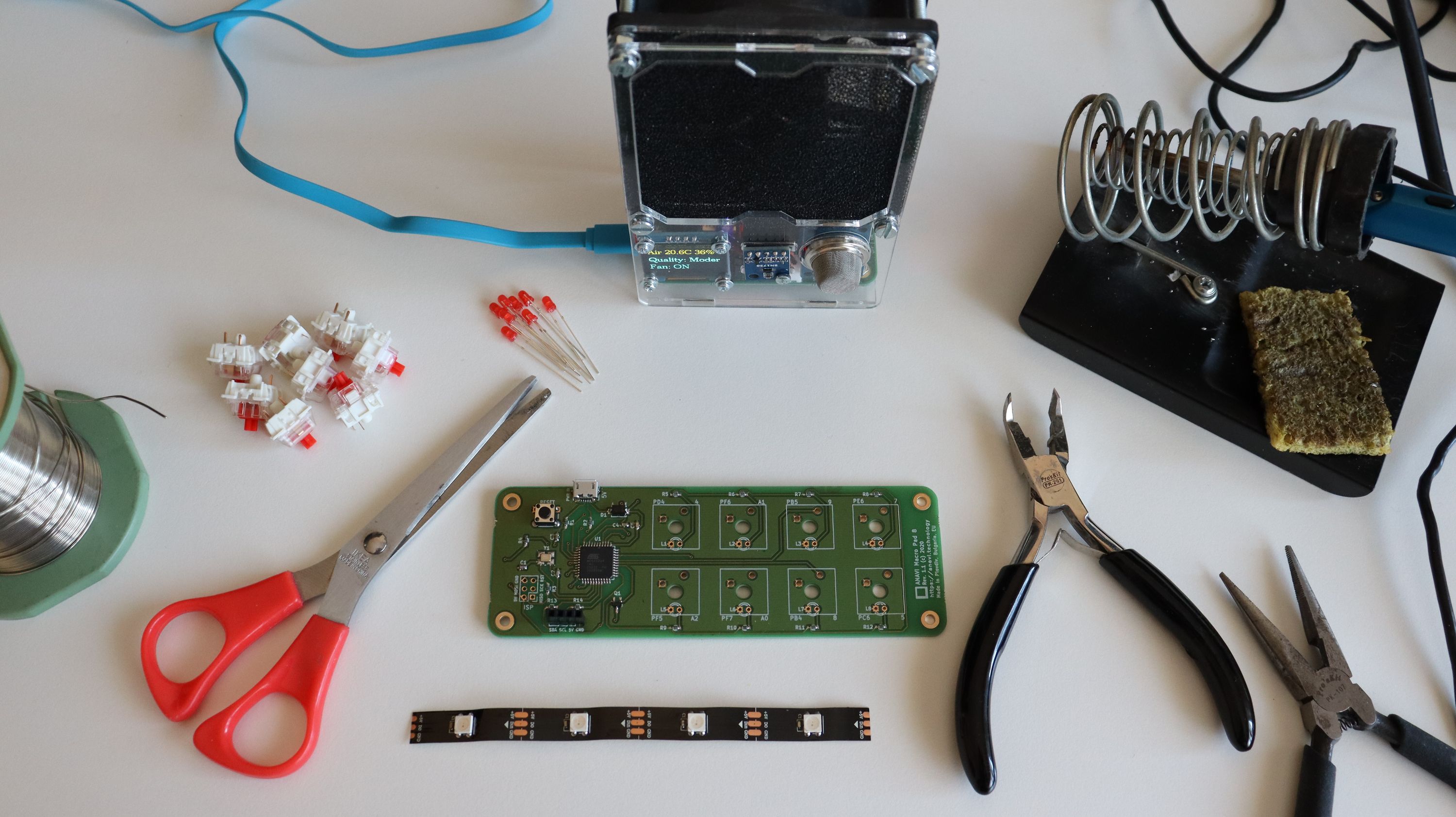
The assembly of ANAVI Macro Pad 8 Maker Kit requires soldering and advanced skills. The following tools are required:
- Soldering iron
- Scissors
- Optional: screwdriver, tweezers and a keycap puller
It is also a good idea to stay safe and get a smoke absorber while soldering, for example our open source ANAVI Fume Extractor.
Please have a look at the video and follow the steps below if you have ANAVI Macro Pad 8 Maker Kit.
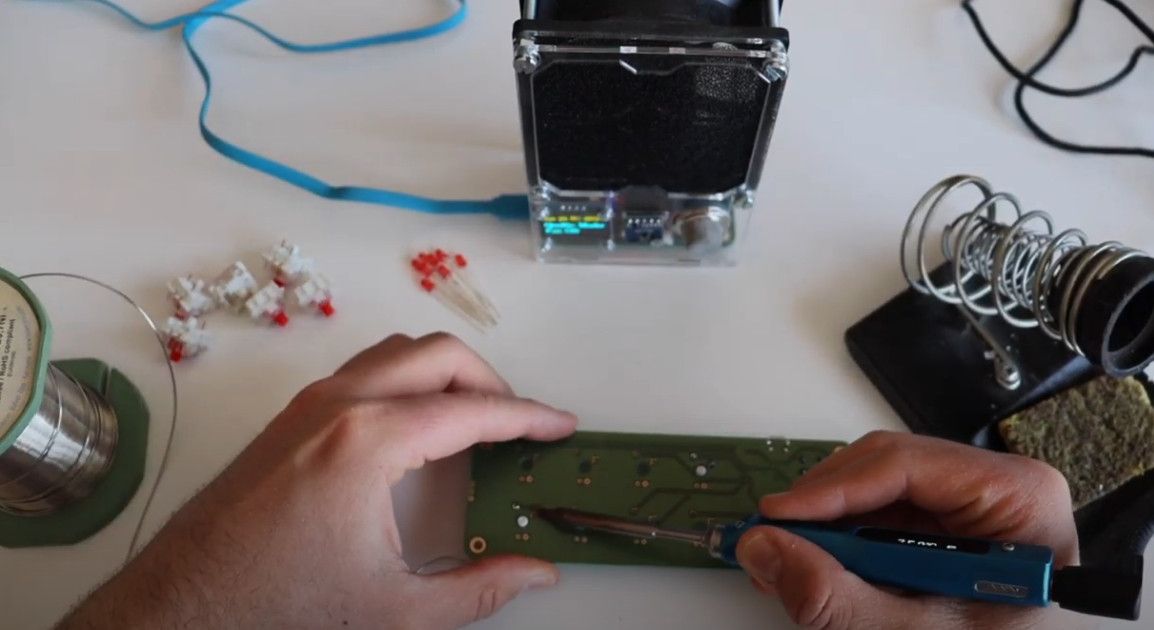
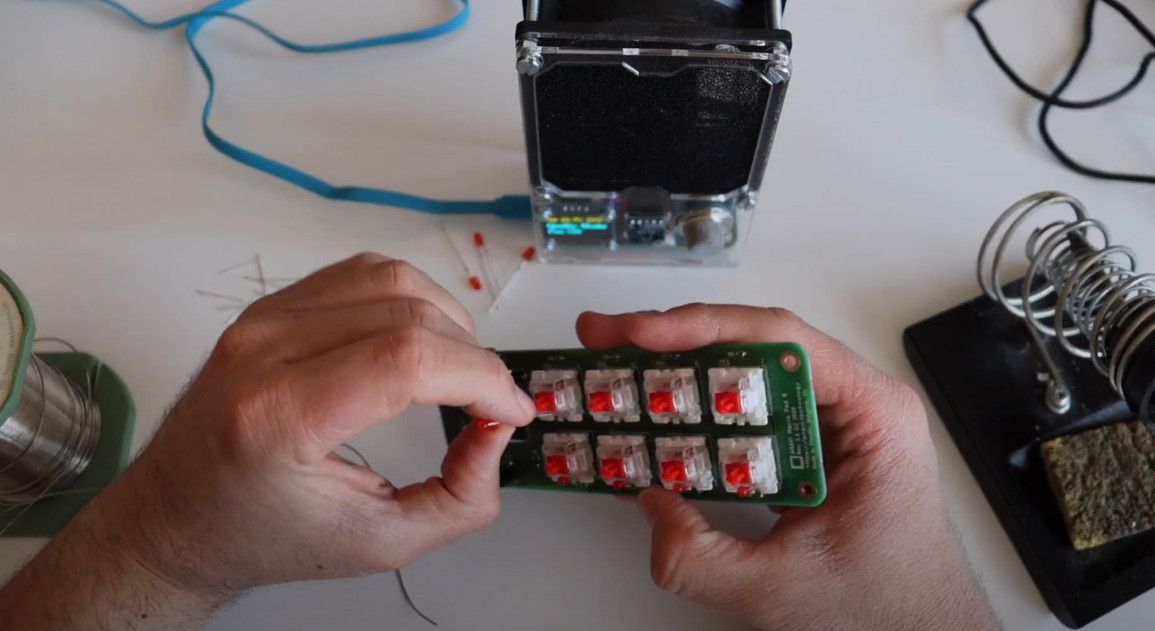
Step 1: Solder mechanical switches to the PCB
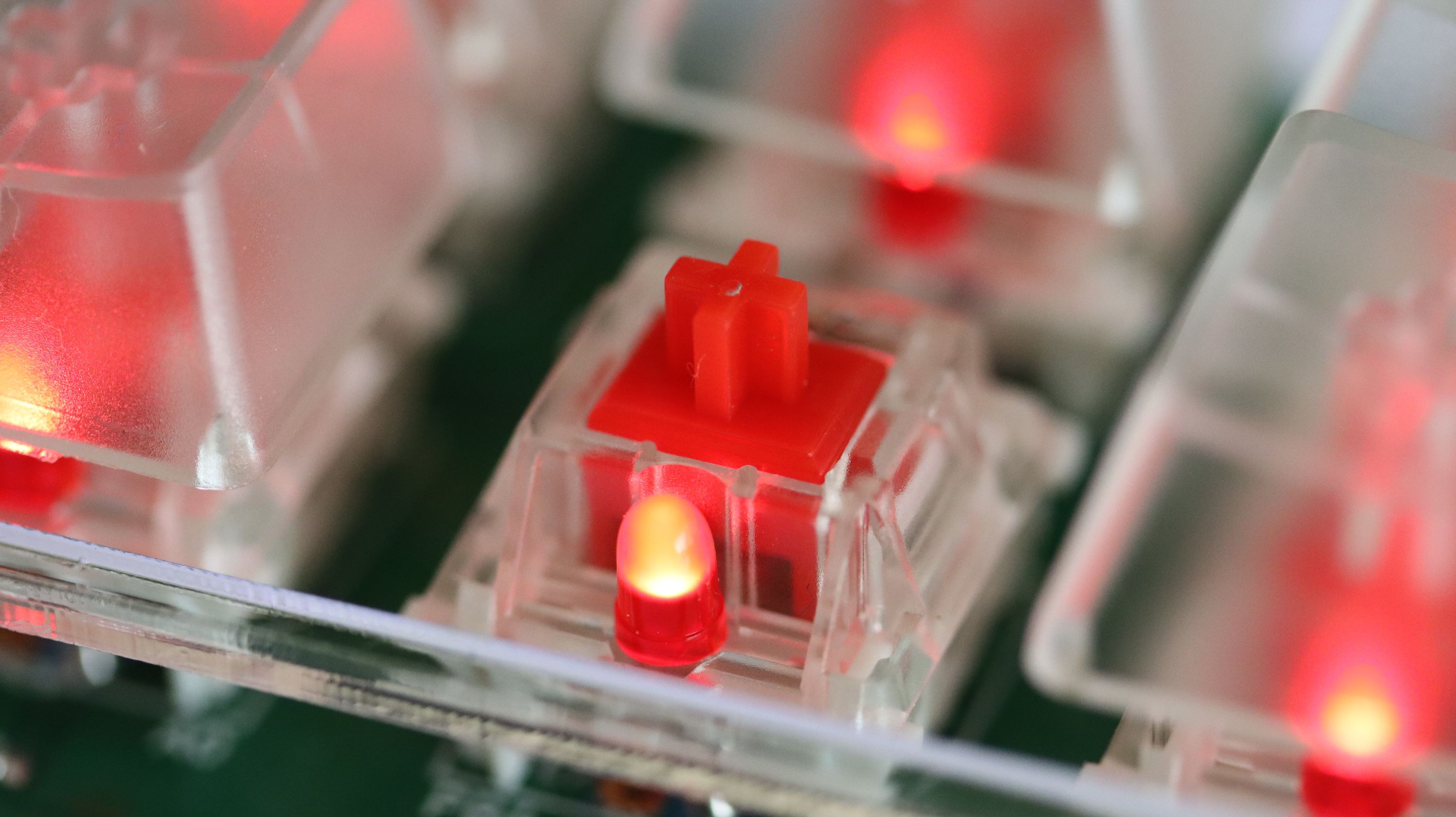
Any type of mechanical switch compatible with Cherry MX plate footprint is suitable for ANAVI Macro Pad 8. The Developer Kit comes with Gateron mechanical switches, while the Maker Kit allows you to use different brand and color.
Choosing the most appropriate switch for your needs and taste is a matter of personal preference. There are many different brands and colors. For example, the blue mechanical switches are more noisy which could be sometimes fun but also annoying during daily work. The red switches are fast and not very noisy therefore they are often proffered by gamers.
There are two pins on each mechanical switch that must be soldered to the printed circuit board. That makes 16 pins in total. The position of the each pin is very specific and the switch goes into the PCB. One of the pins is for the signal coming from the Microchip ATmega32U4 microcontroller, the other pin is for ground.
Step 2: Solder 3 mm LED
This step is actually optional depending on the the type of the mechanical switch. Some mechanical switches may not have a hole in the plastic enclosure for a 3 mm LED.
Each 3 mm LED for through-hole soldering has 2 legs. The longer leg is the positive terminal, also known as anode. The shorter leg is negative and also known as cathode.
The shorter leg that indicates the negative terminal must go into the square hole of the PCB. ANAVI Macro Pad 8 has 8 mechanical switches therefore 8 LEDs are required. If you want you can use different color of the LEDs. You can even mix colors.
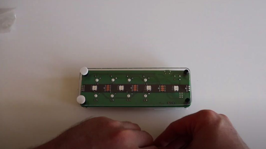
Step 3: Solder WS2812B addressable LED strip to the back of the PCB
Using scissors cut a little bit from both ends of the LED strip to make sure it will stretched when placed on the board. However it is tricky, be careful and make sure enough from the pads are available to make a good contact after soldering them.
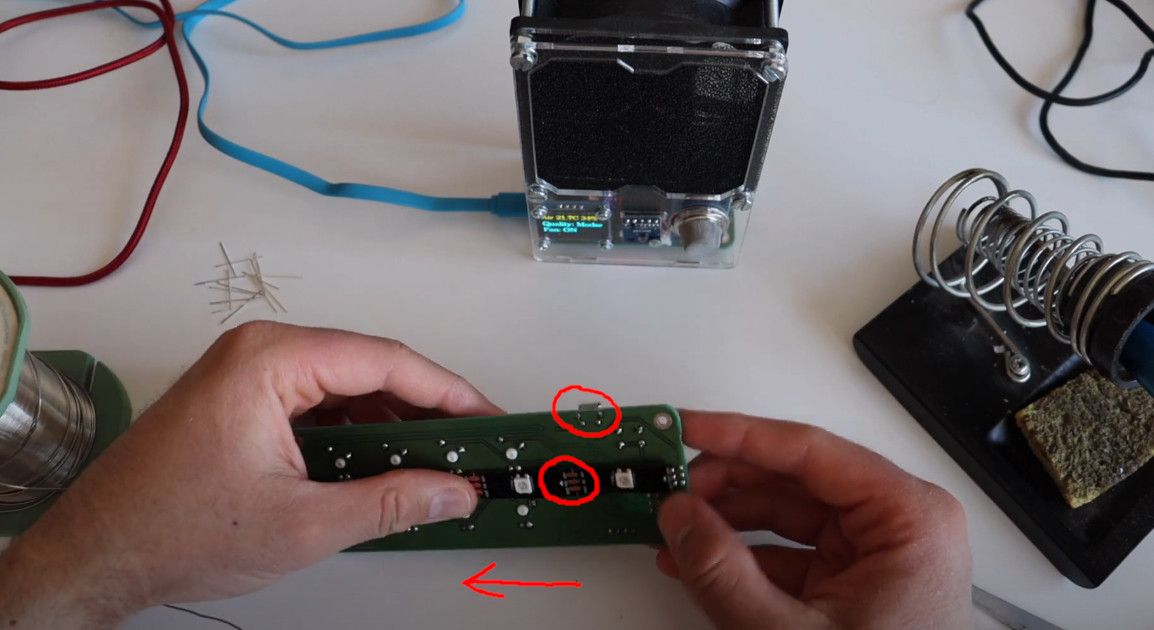
It is very important to properly set the direction of the WS2812B LED strip. On the LED strip you will notice small arrows indicating the direction. They should point from the microUSB connector towards the other end of the PCB as shown in the video.
NOTE: Once you are ready with these 3 steps your ANAVI Macro Pad 8 should look just like a Developer Kit, will all accessories soldered. Therefore the next steps are the same as for both the developer and the Maker Kit.
Step 4: Stickers
The first step is optional. Each kit includes a set of stickers. Feel free to add them to the translucent keycaps. You can do it with your bare hand or eventually with the help of tweezers.
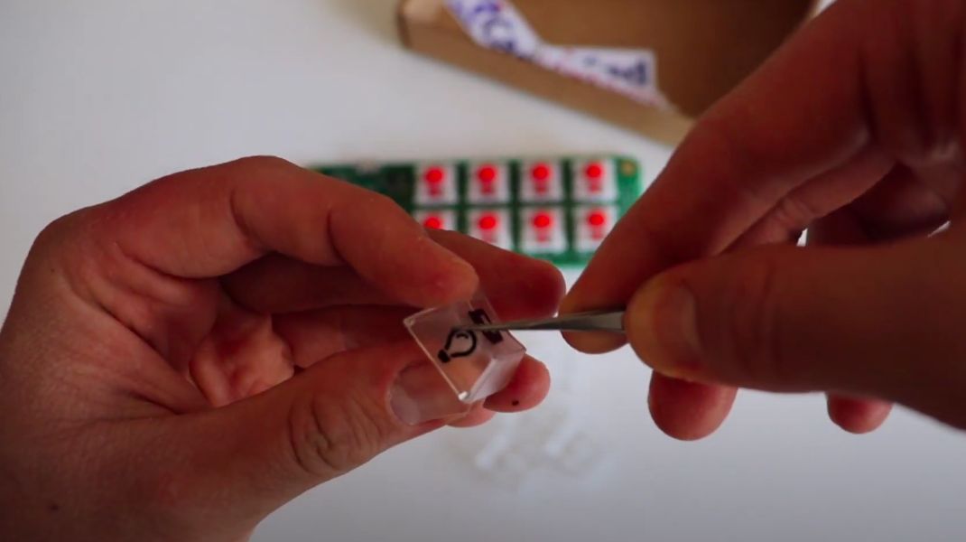
ANAVI Macro Pad 8 is powered by the popular open source firmware QMK which allows you to create various layouts. You can make a keymap with 2 or more layouts. A sticker on the side of the keycap might be useful as a visual aid to indicate the additional function of the key.
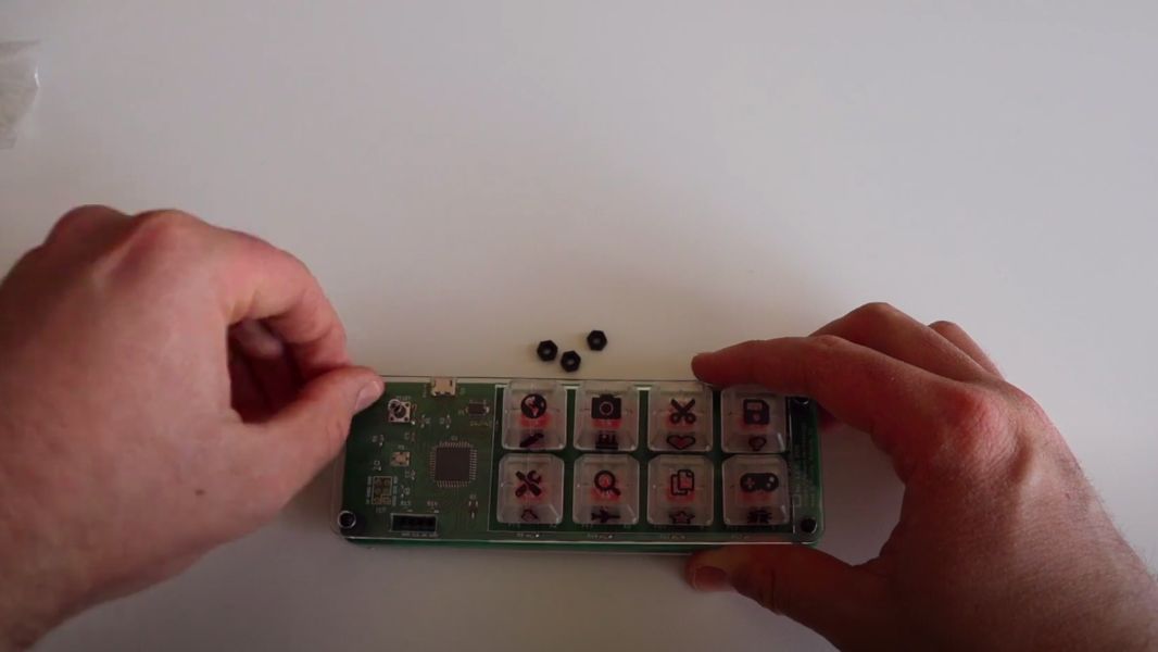
Step 5: Keycaps
Place all keycaps on the 8 mechanical switches of ANAVI Macro Pad 8. You can easily do this with your bare hands. It takes just a few seconds.
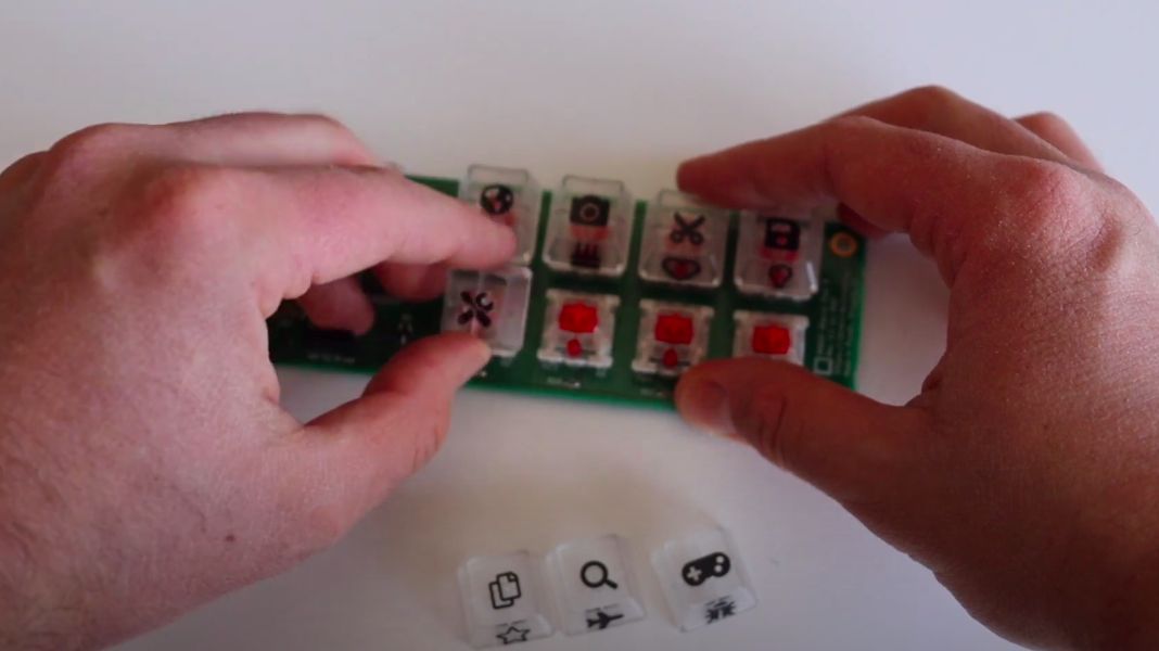
As you can see in the video, a keycap puller might be useful if you make a mistake and want to pull off a keycap and place it on another location.
Step 6: Peel Off Protective Films from the Acrylic Enclosure
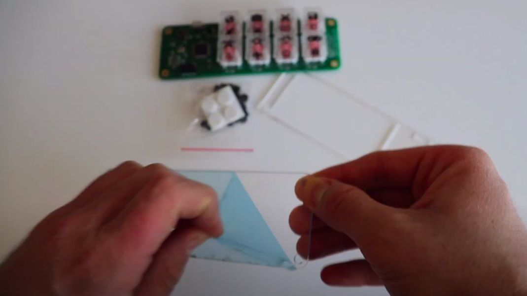
Peel off the protective films from both sides of the two laser cut transparent acrylic parts. The removal of the protective films is quite annoying but once you get rid of them, the acrylic enclosure will be crystal clear and fully transparent.
Step 7: Assemble the Acrylic Enclosure
Assemble the acrylic enclosures. In the cardboard box you also will find M3 black plastic screws, nuts and standoffs. Although you can assemble them with your bare hands a screw driver might be handy.
First place 4 of the stand-offs with screws to the bottom acrylic part. After that, place ANAVI Macro Pad 8 on top of them. The printed circuit board has 4 mounting holes for this purpose.
Add the rest of stand-offs on top of the ANAVI Macro Pad 8 to secure the printed circuit board to the bottom part as shown in the video. Place the top acrylic part and fasten it with the 4 M3 nuts. Finally add the silicon protective pads to the screws on the bottom.
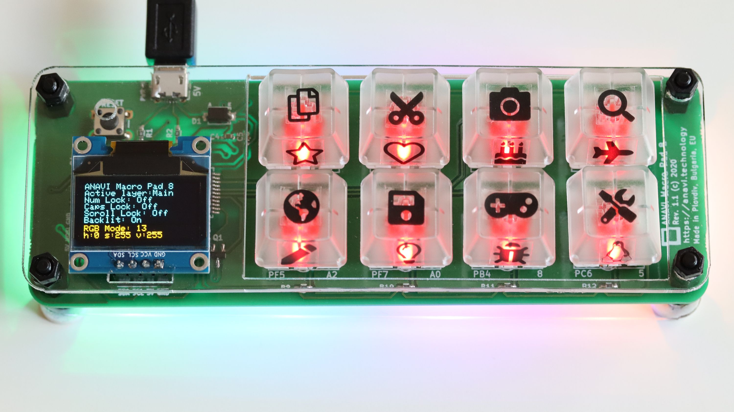
Step 8: Mini OLED Display
Step number 5 is optional. The default open source QMK firmware for ANAVI Macro Pad 8 support mini OLED display connected over the communication bus I2C.
By default. the mini display is in yellow-blue 0.96" I2C OLED. It comes with 4 jumper wires which might be useful for debugging purposes or if you plan to make a custom 3D printed case. However for the default acrylic enclosure the wires are not needed.
Peel off the protected film and place the mini OLED display as shown in the video to ANAVI Macro Pad 8. Pay attention to the labels that indicated the pin connectors of the display. They must match the labels on the keyboard.
Step 9: Turn On ANAVI Macro Pad 8
Gently use a USB to microUSB cable to connect ANAVI Macro Pad 8 to a personal computer. Please be careful with the microUSB connector, because a harsh bending of the USB cable may damage the microUSB connector.
Thanks to the QMK firmware, ANAVI Macro Pad 8 will be detected as human interface device and should work out of the box. Furthermore with QMK you have the freedom to fully customize each key.
Please note that a USB to microUSB cable is not included in any of the kits. Reuse a cable from an old electronic device or purchase a cable according to your taste. Make sure that the cable supports both power and data transfer over USB.
Thank you for supporting and using our open source kits. Stay tuned for more updates, tips and tricks!
Thanks, Leon