Project update 9 of 16
[VIDEO] ANAVI Gas Detector Assembly Guide
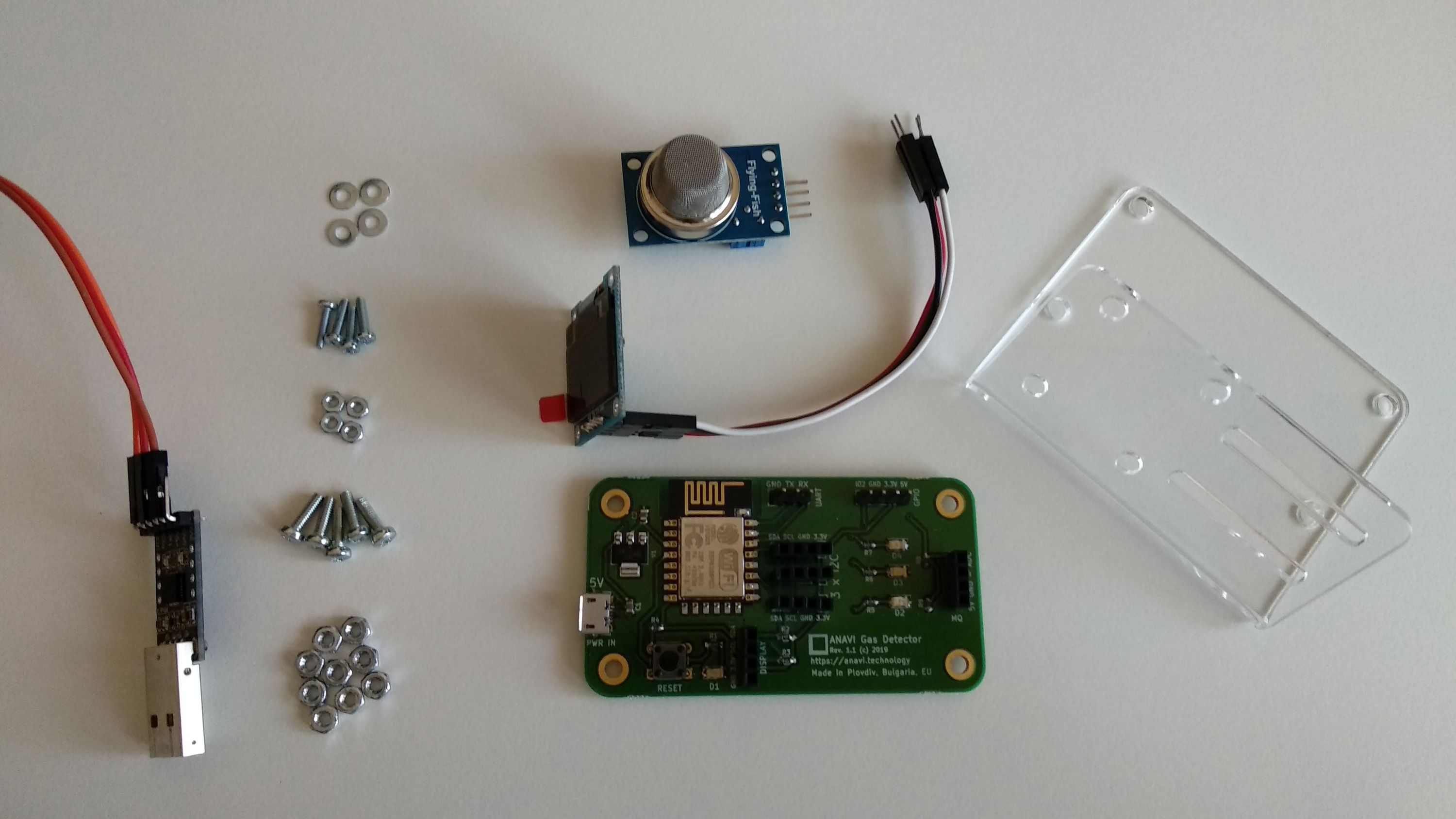
All kits of ANAVI Gas Detector include MQ-135 sensor module, USB to UART debug cable, an acrylic stand and a mini OLED I2C display. The stand has been designed using the free and open source software OpenSCAD. The schematics are available at GitHub. The printed circuit board of ANAVI Gas Detector has the same dimensions as the one for ANAVI Thermometer so actually both use the same acrylic stand.
I have recently shared ANAVI Gas Detector assembly guide which is available at my YouTube channel. The whole process takes about 10 minutes. You will need a screwdriver. Please find below the exact steps with additional details.
For the video I used a starter kit with ANAVI Gas Detector. Appropriate nuts, screws and washers are included.
Step 1
Peel off the protective film from the acrylic stand. Also remove the protective film from the display.
Step 2
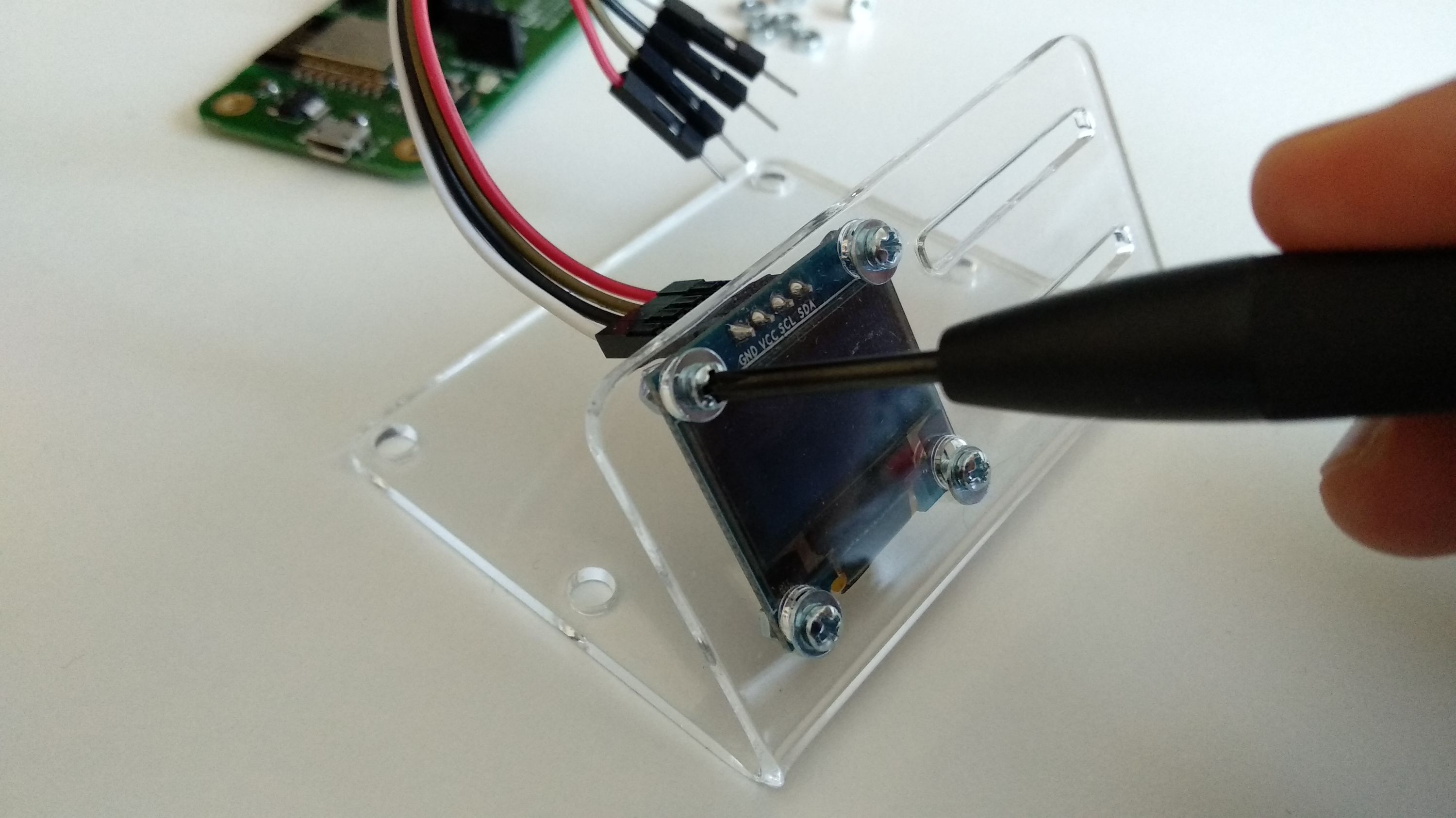
Using a screwdriver, gently attach the mini OLED display to the acrylic stand with the M2 screws and nuts as shown on the photo. The mini OLED display is fragile so please be very careful. Do NOT fasten it too tight because the torque may break it.
Step 3
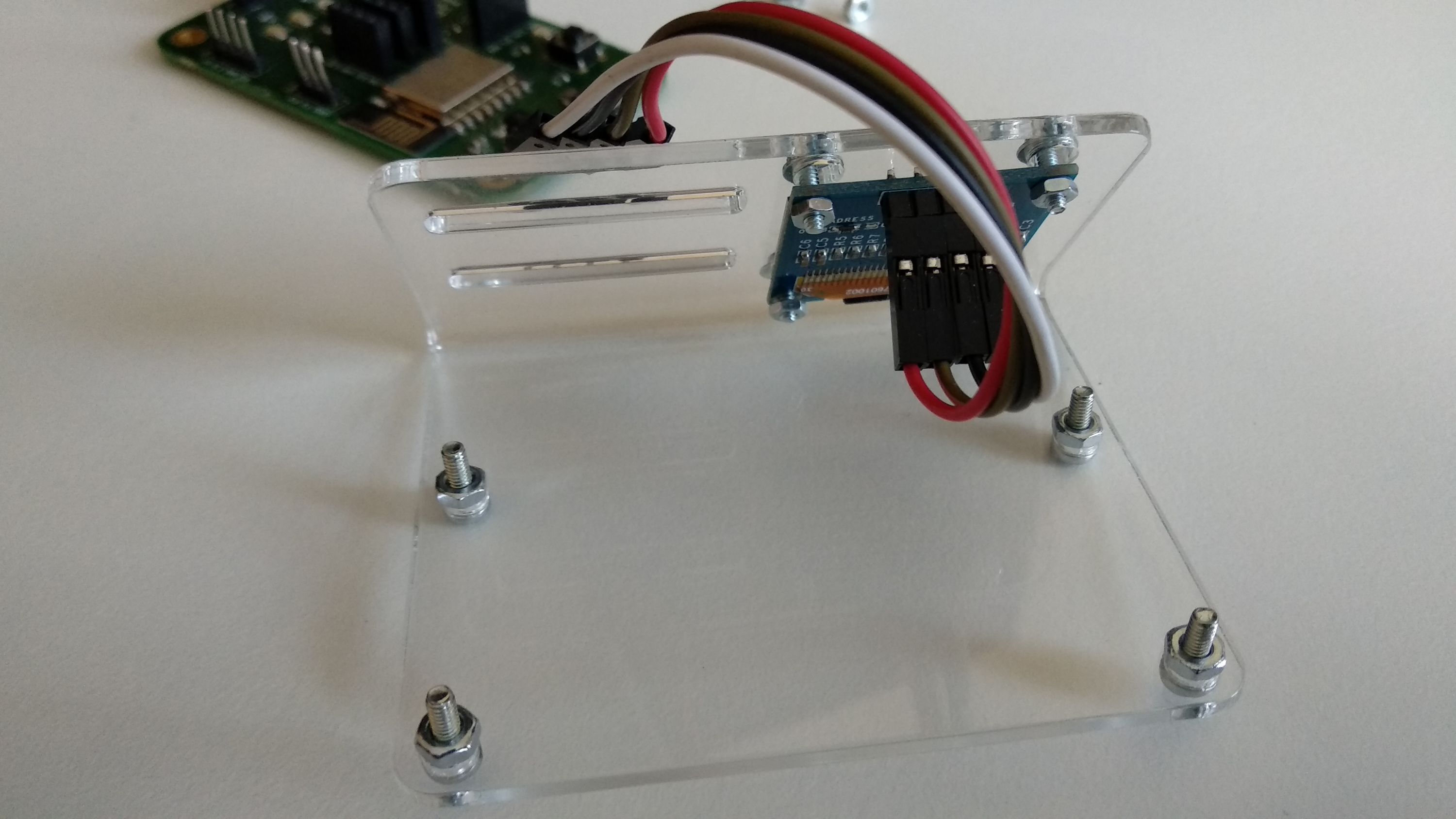
Add four M2.5 screws and nuts to the case of the acrylic stand. In the next step we will put ANAVI Gas Detector on top of the nuts.
Step 4
Add ANAVI Gas Detector on top of the nuts and fasten it with the additional M2.5 nuts. At the end you will have a spare M2.5 screw and nut to optionally attach an additional sensor to the acrylic enclosure.
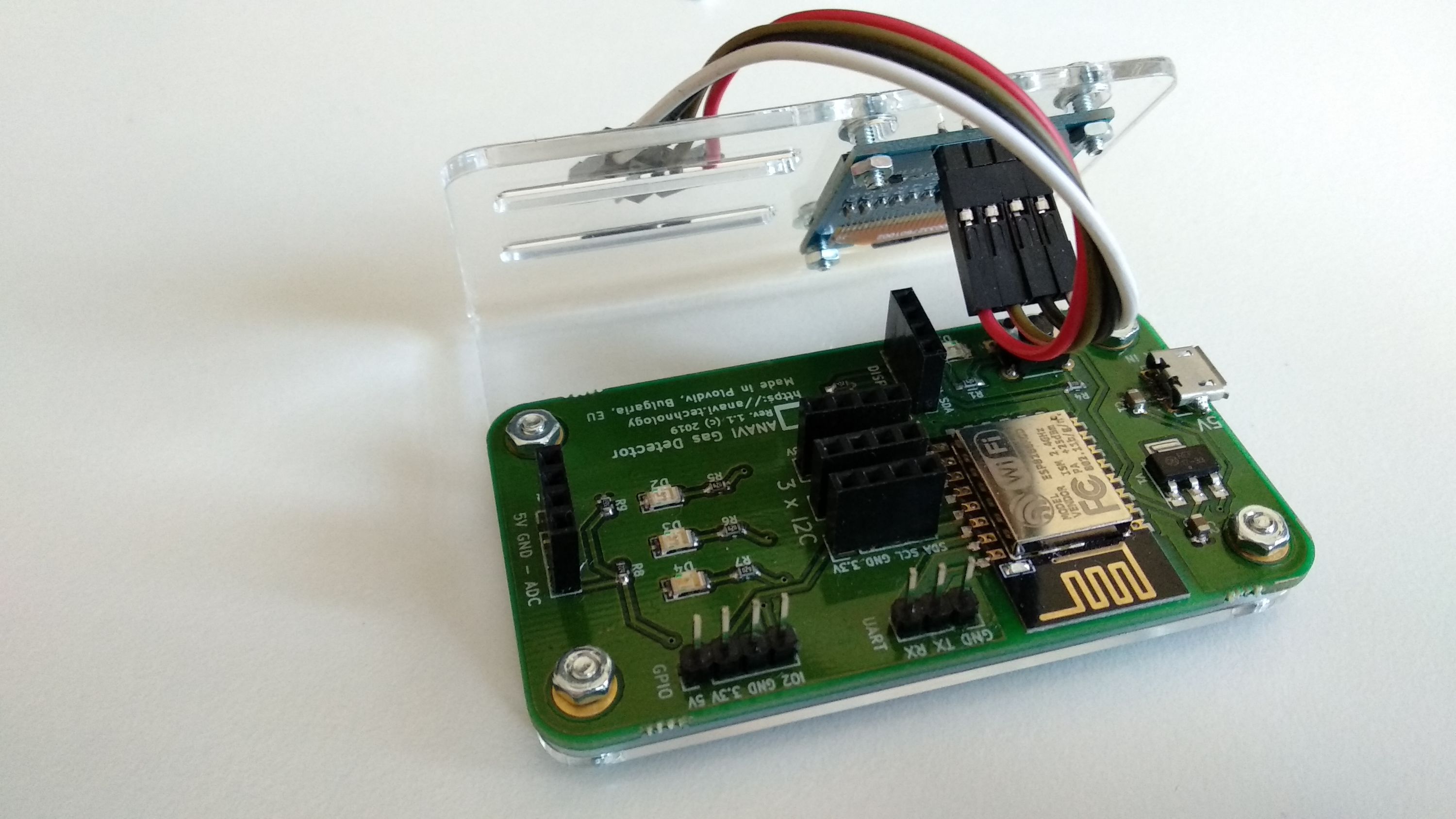
Step 5
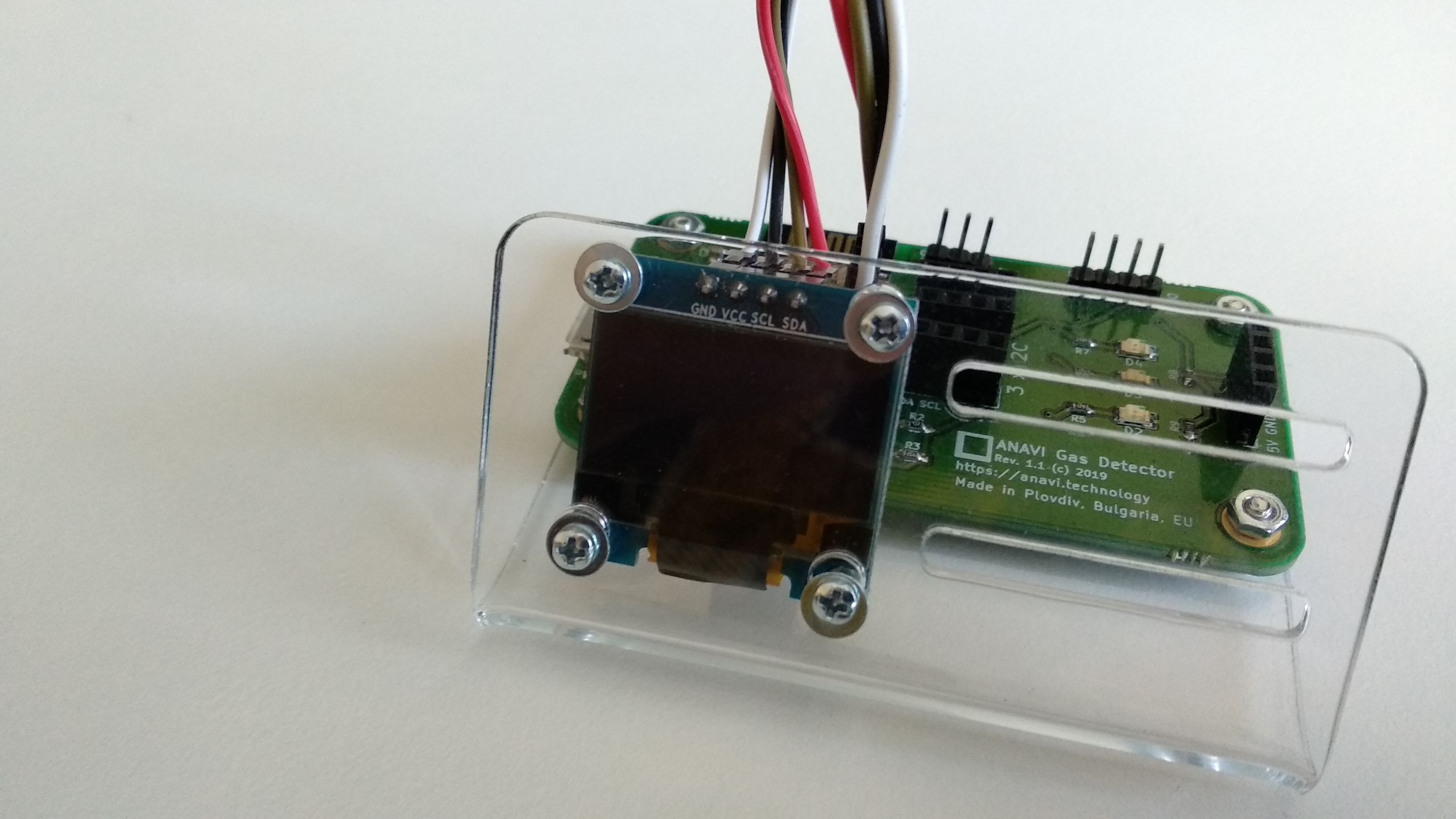
Gently connect the mini OLED display to the dedicated slot using the male to female jumper wires. The colors of the wires do not matter. Just have a look at the labels on the top of the OLED display and connect each of the four pins to a pin with the same label on the dedicated slot for the display on ANAVI Gas Detector.
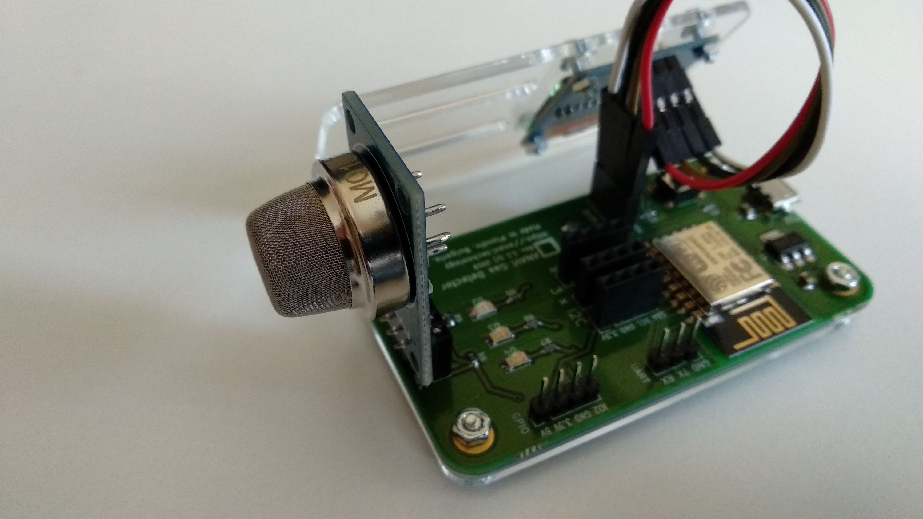
Plug the MQ-135 sensor module in slot labeled as MQ. Owners of Advanced or Developer kit should also plug the additional I2C sensor modules.
Finally, you are ready to turn on and enjoy ANAVI Gas Detector! On first boot you need to configure and connect ANAVI Gas Detector to your WiFi network.
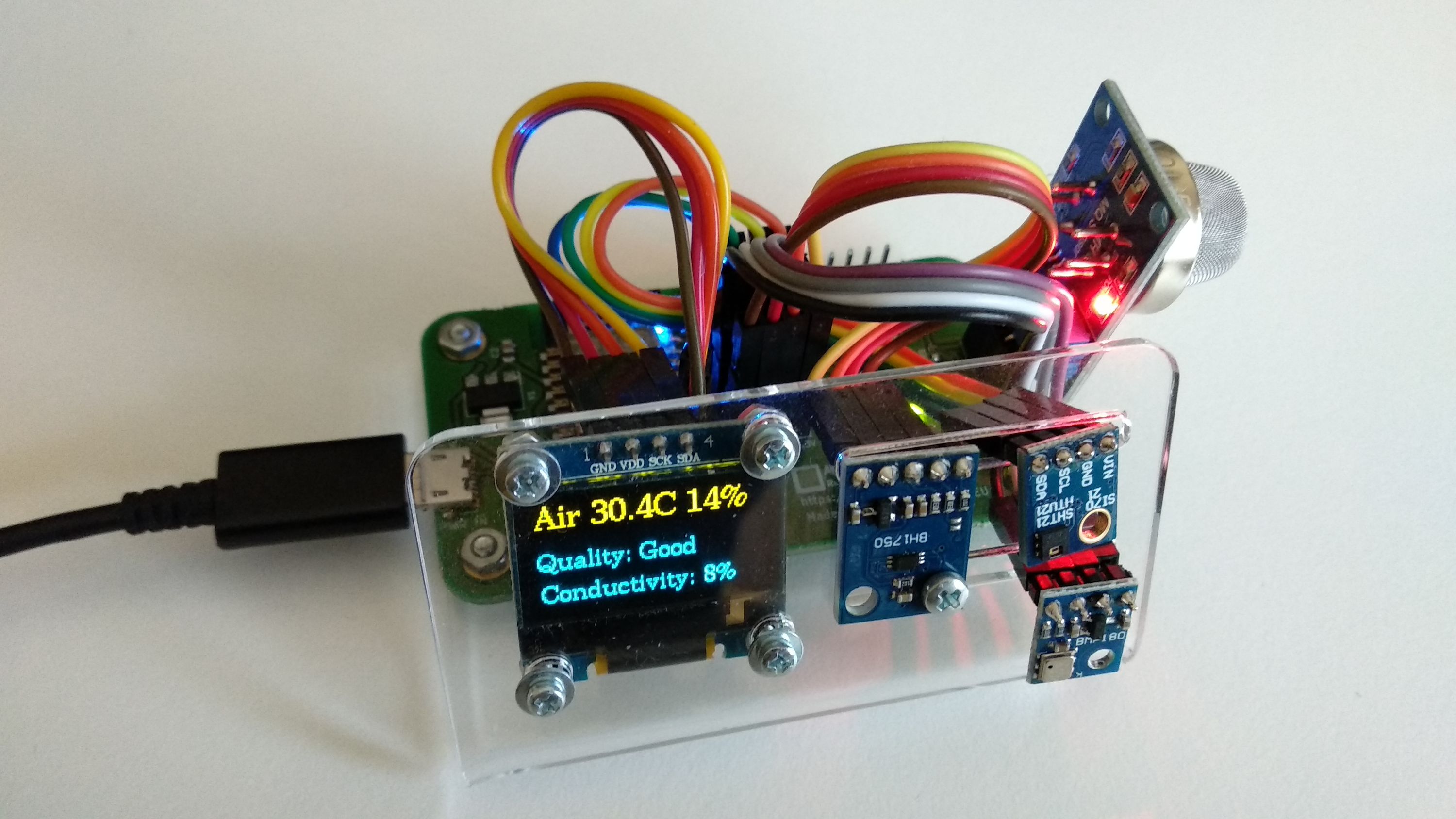
On the first boot it is also very important to do the so called "burn-in" procedure for initial calibration of MQ-135. Place ANAVI Gas Detector with MQ-135 sensor module in a room with clean air and leave it running for at least 24 hours. This has to be done only once when MQ-135 sensor module is used for the first time. After doing this procedure, on every next boot ANAVI Gas Detector and MQ-135 will do a quick calibration in couple of minutes and start working properly. Just have a look at the video to do the whole process easier and to learn more.
Thank you for supporting this entirely open source project. In next article we will share the exact steps how to connect ANAVI Gas Detector your WiFi network. Stay tuned for more updates!
Best regards,
Leon