Project update 10 of 13
[VIDEO] ANAVI Miracle Controller Assembly Guide
by ANAVI TechnologyAll kits of ANAVI Miracle Controller include USB-to-UART debug cable and a couple of addressable (digital) WS2812B LED strips with appropriate connector and a choke resistor. Both the advanced and the developer kits also include acrylic stand, mini OLED display and BH1750 I2C sensor module for light. The developer kit is equipped with APDS-9960 gesture and color recognition sensor as well as BMP180 temperature and barometric pressure sensor.
This video tutorial covers the exact steps to assemble ANAVI Miracle Controller Advanced Kit.
Step 1
Peel off the protective film from the acrylic stand. Also remove the protective film from the display.
Step 2
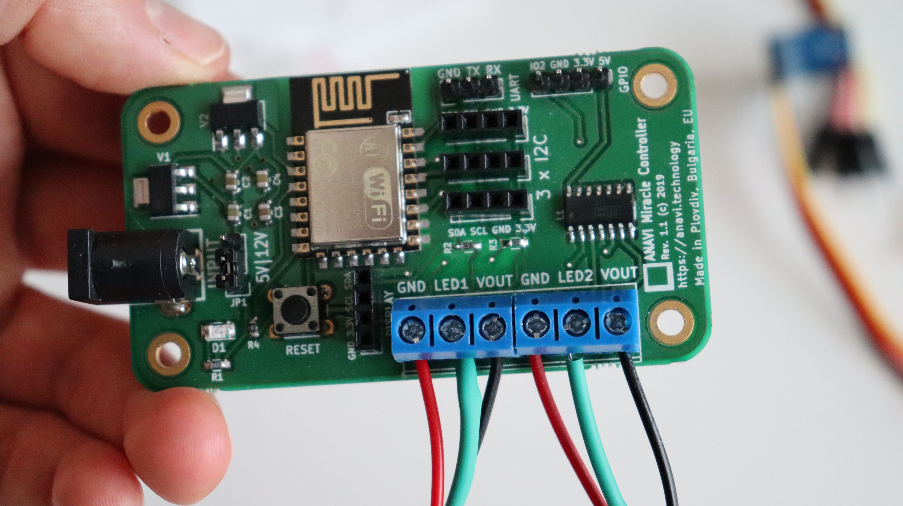
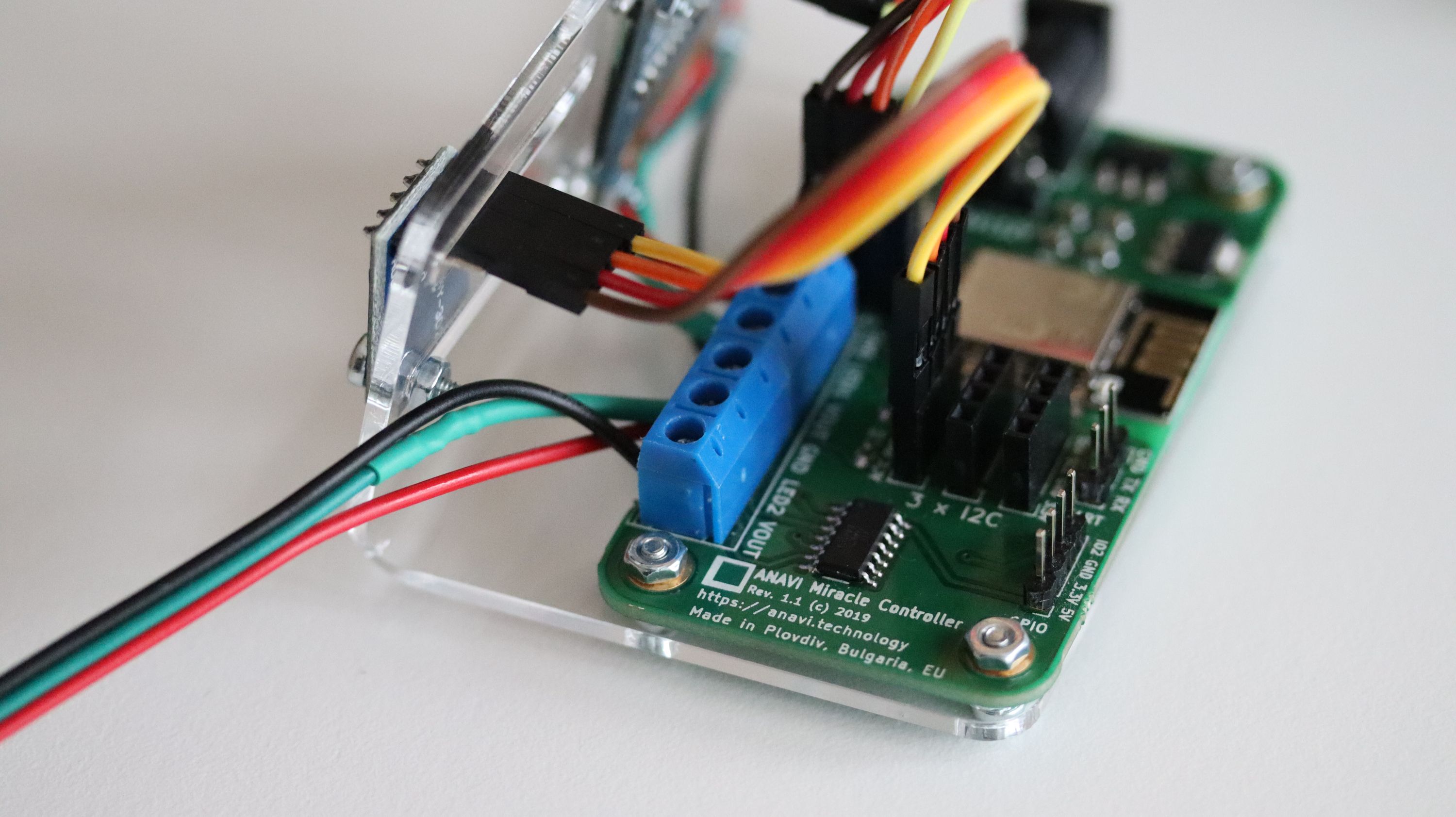
Connect the addressable WS2812B LED strips to ANAVI Miracle Controller. Each strip has connector with a choke resistor.
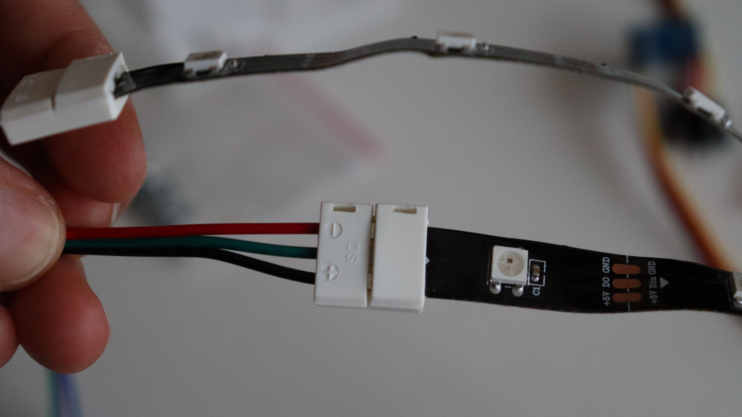
- Red wire - GND (connect to GND on ANAVI Miracle Controller)
- Green wire - Data (connect to LED1 or LED2 on ANAVI Miracle Controller)
- Black wire - 5V (connect to VOUT on ANAVI Miracle Controller)
Beware the colors of wires. If you are using a different LED strip or a connector the colors might be different!
Step 3
Using a screwdriver, gently attach the mini OLED display to the acrylic stand with the M2 screws and nuts as shown on the photo. The mini OLED display is fragile so please be very careful. Do NOT fasten it too tight because the torque may break it. Have a look at the video for details.
Step 4
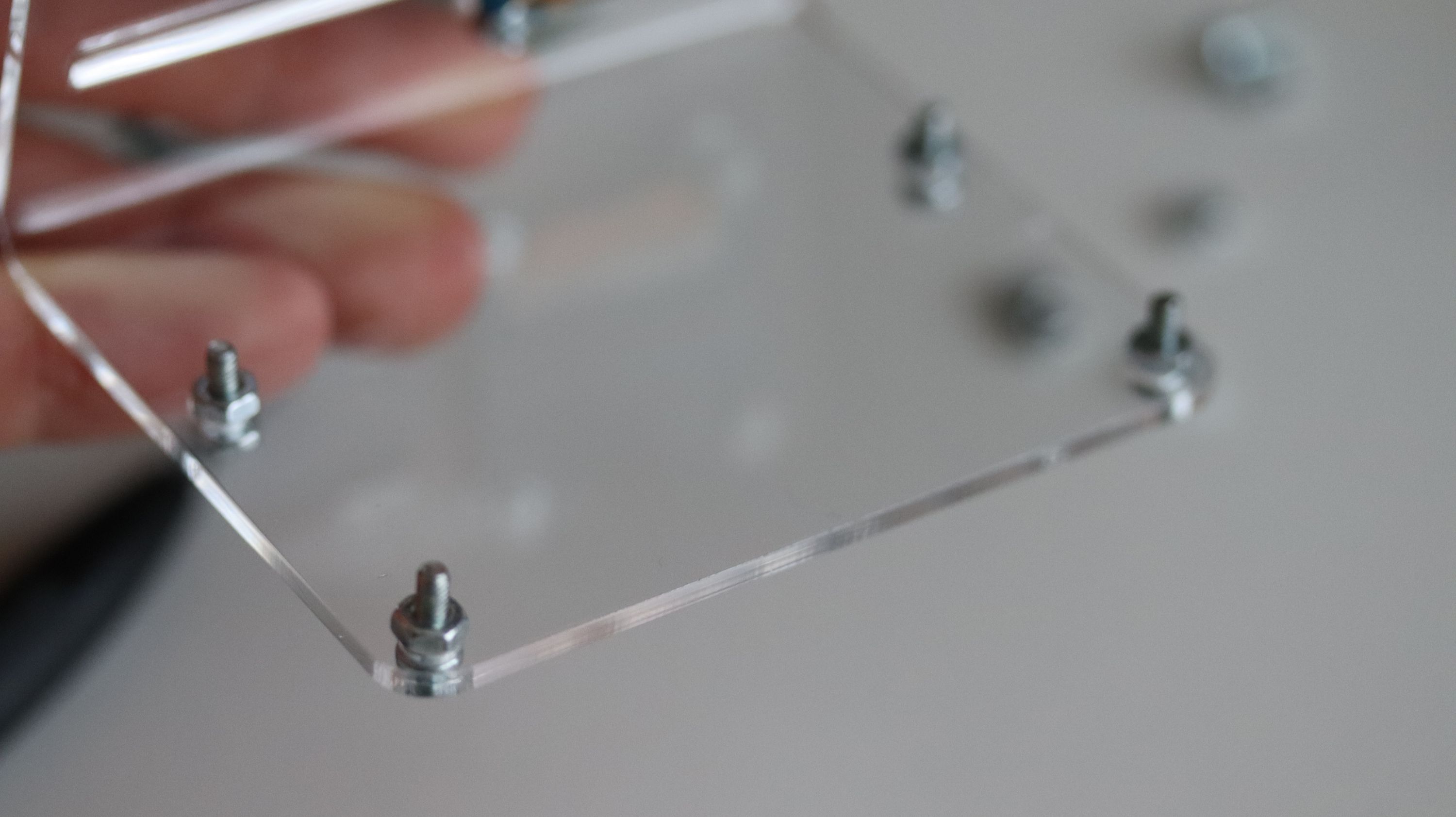
Add four M2.5 screws and nuts to the case of the acrylic stand. In the next step we will put ANAVI Miracle Controller on top of the nuts.
Step 5
Add ANAVI Miracle Controller on top of the nuts and fasten it with the additional M2.5 nuts. As you can see in the video, there are two options how to place ANAVI Miracle Controller: with LED strips pointing towards the OLED display or in the opposite directory. Both ways are OK and it is up to you to decide.
At the end you will have a spare M2.5 screw and nut to optionally attach BH1750 sensor to the acrylic enclosure.
Step 6
Gently connect the mini OLED display to the dedicated slot using the male to female jumper wires. The colors of the wires do not matter. Just have a look at the labels on the top of the OLED display and connect each of the four pins to a pin with the same label on the dedicated slot for the display on ANAVI Miracle Controller.
Step 7
Attached I2C sensor modules to the dedicated slots. It is recommended to place BH1750 next to the OLED display on front of the acrylic stand.
Step 8
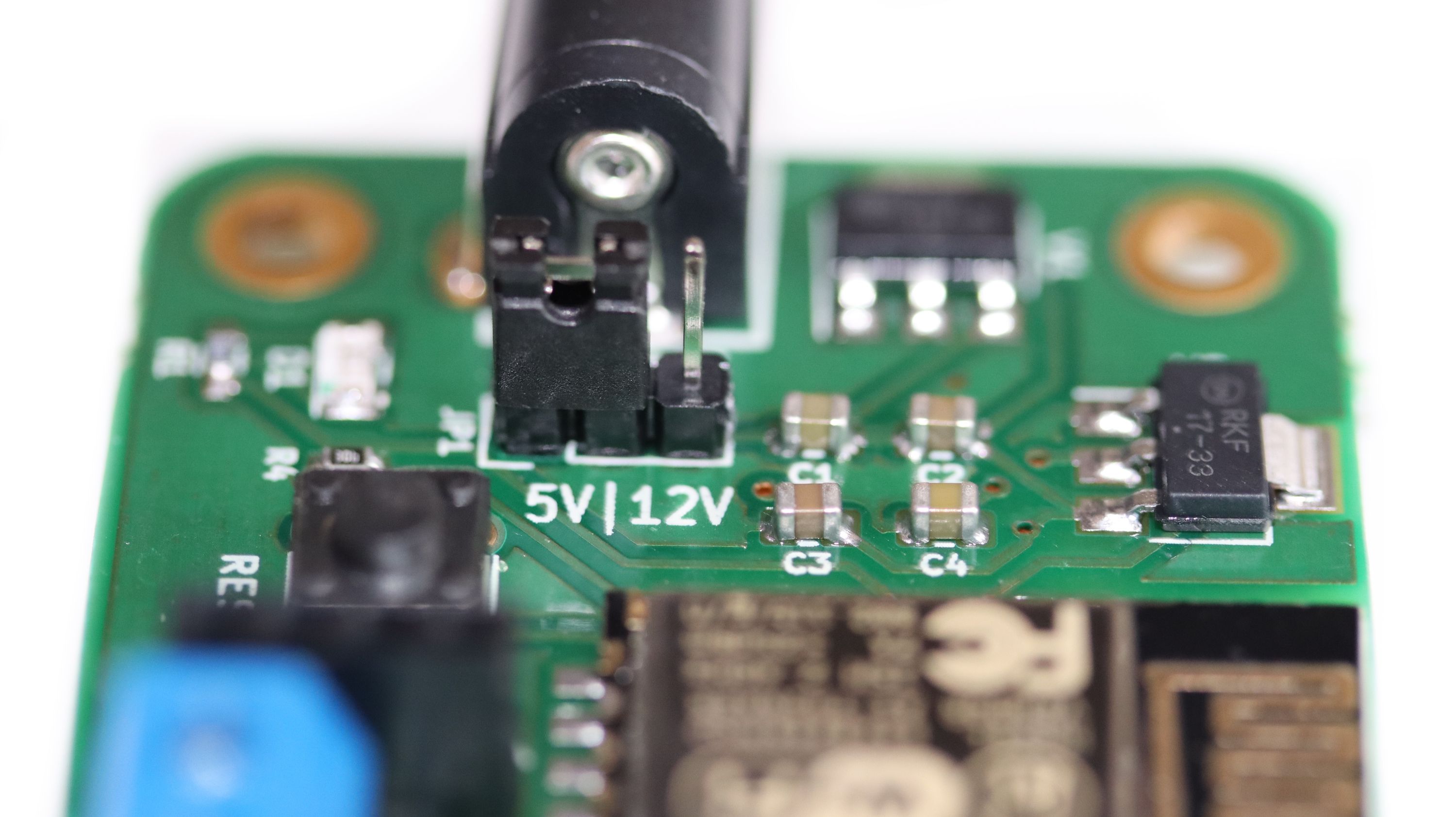
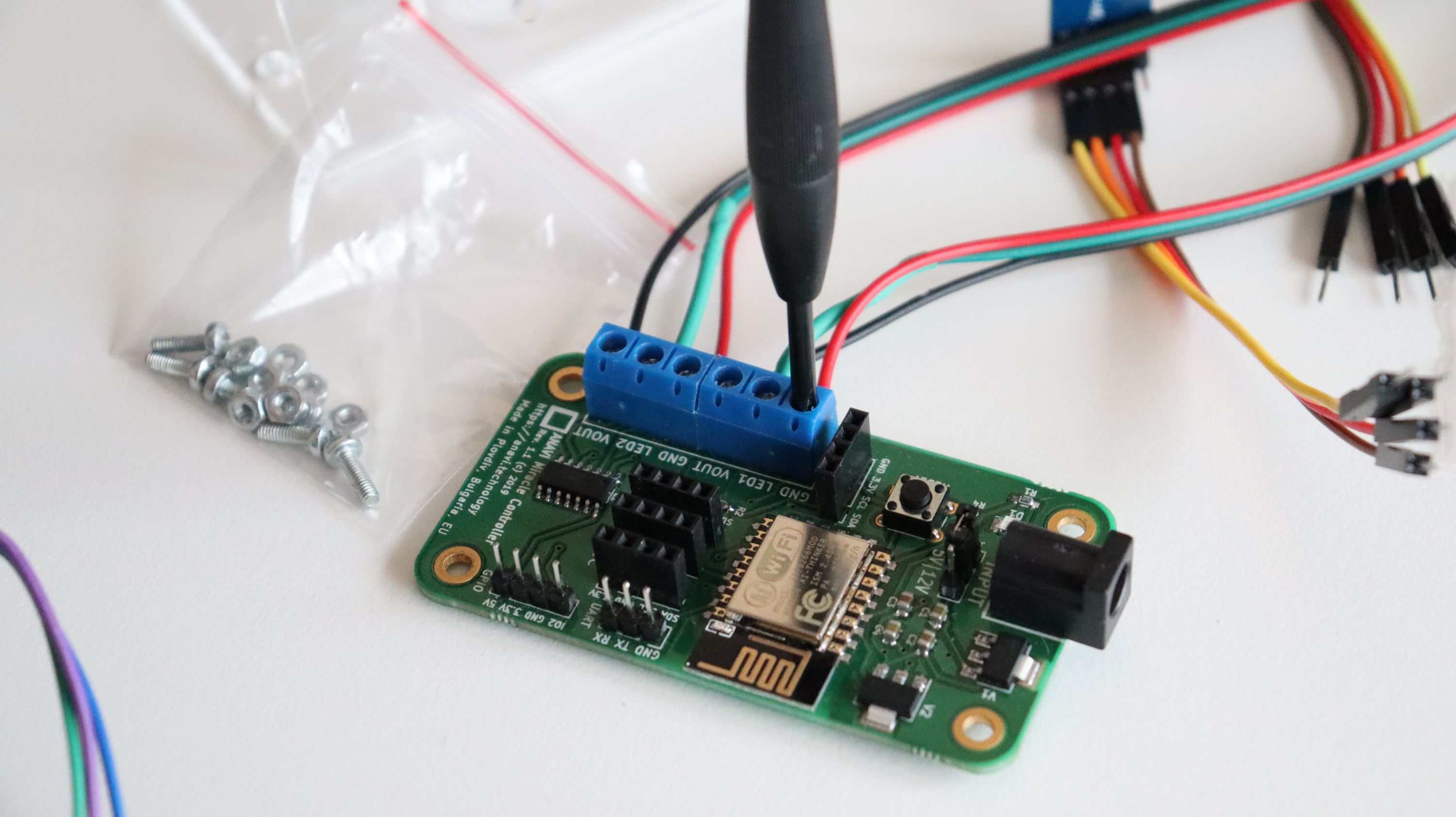
The addressable WS2812B LED strips included in the kits operate at 5V. Set the jumper on the board to 5V. Use an appropriate 5V center positive power supply, for example MEANWELL GST18E05-P1J.
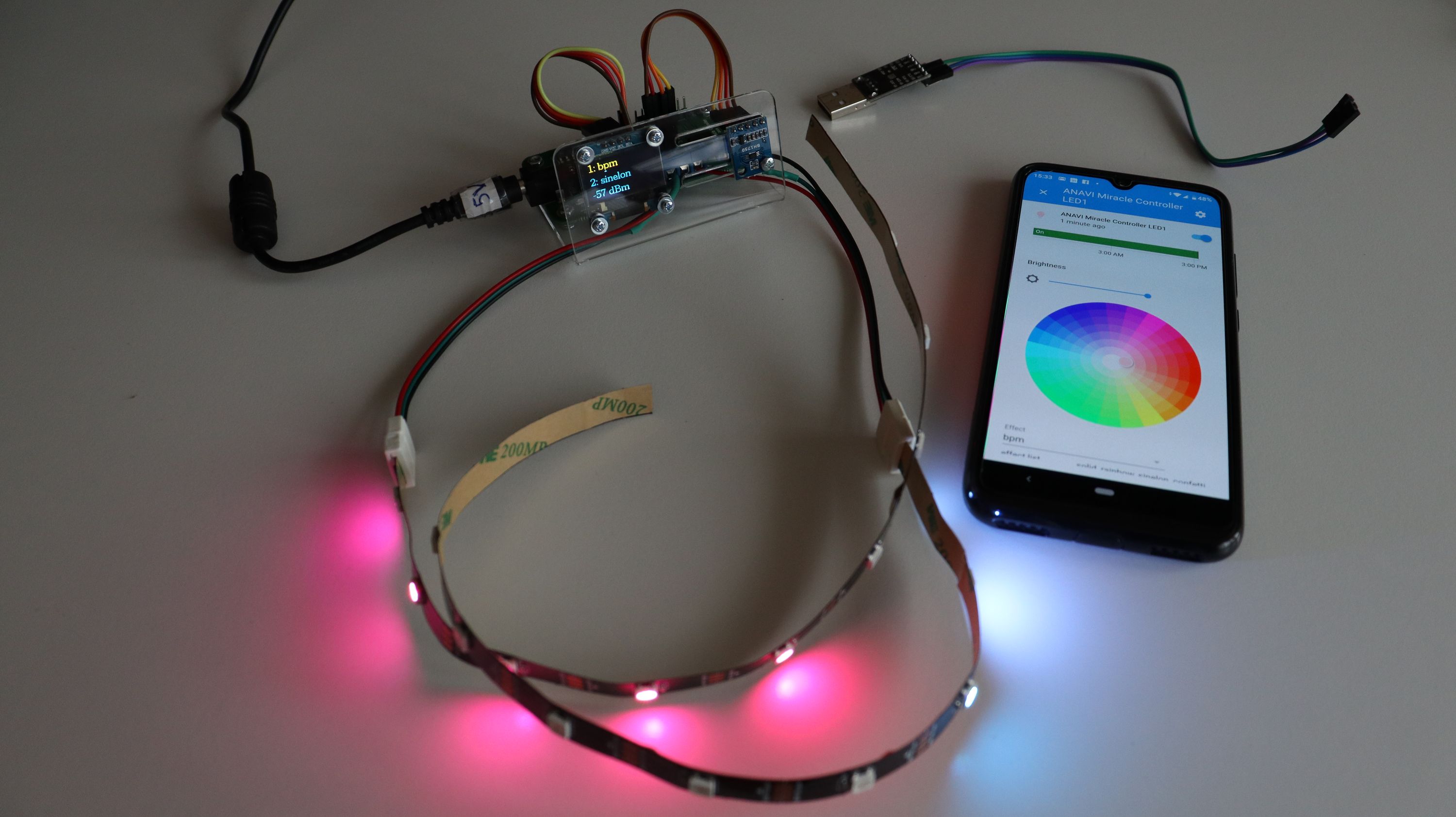
Finally, you are ready to turn on and enjoy ANAVI Miracle Controller! On first boot you need to configure and connect ANAVI Miracle Controller to your WiFi network as explained on the previous update.
It is recommended to update the default open source firmware to the latest version. Out of the box it works with the popular open source home automation platform Home Assistant.
Please have a look at the video tutorial for more details. The user’s manual is available at GitHub.
Thank you for supporting the crowdfunding campaign of ANAVI Miracle Controller. With your help we will continue improving the firmware and we will release more updates how to use the board.
Best regards,
Leon