Project update 5 of 13
Syncronizing Haasoscope vs. Haasoscope Pro
by Andy HaasHaasoscope Pro Hits Funding Goal!
Dear Haasoscope fans,
First of all—thanks to your support, the Haasoscope Pro has met its funding goal! We have about a week left in the campaign, which means now is the time to grab your unit at the lowest campaign price. Once the campaign ends, an order will quickly be placed for parts and boards, based on the already validated final hardware design. I’ve already pre-ordered any parts that could have longer lead times, so there should be no delays in getting the units to backers.
We also now have a third member of the development team, Glenn K., bringing years of FPGA and embedded expertise. If others are interested in joining the team, get in touch—I still have several prototype boards that could be sent out for developing and testing.
Expandable by Design
For this week’s update, I want to focus on a key feature of Haasoscopes—expandability. By connecting Haasoscopes together, you can seamlessly increase the number of channels available. All the channels will act like they’re part of the same scope. Any channel can be used for triggering, and it will trigger the synchronized readout of all channels on all units.
How Many Can You Connect?
The only limit is that each unit needs a USB2 connection to the computer. A single USB2 controller can support up to 127 units, though you’d start to be bandwidth limited around ~20 units given the ~1 MB/s readout rate. If that wasn’t enough, you could always add more USB2 controllers to your computer.
This feature actually dates back to the original Haasoscope. Here’s a picture from my lab at NYU where 16 Haasoscopes are daisy-chained together. Each of the original Haasoscopes was 4 channels, so this is a 64-channel oscilloscope!
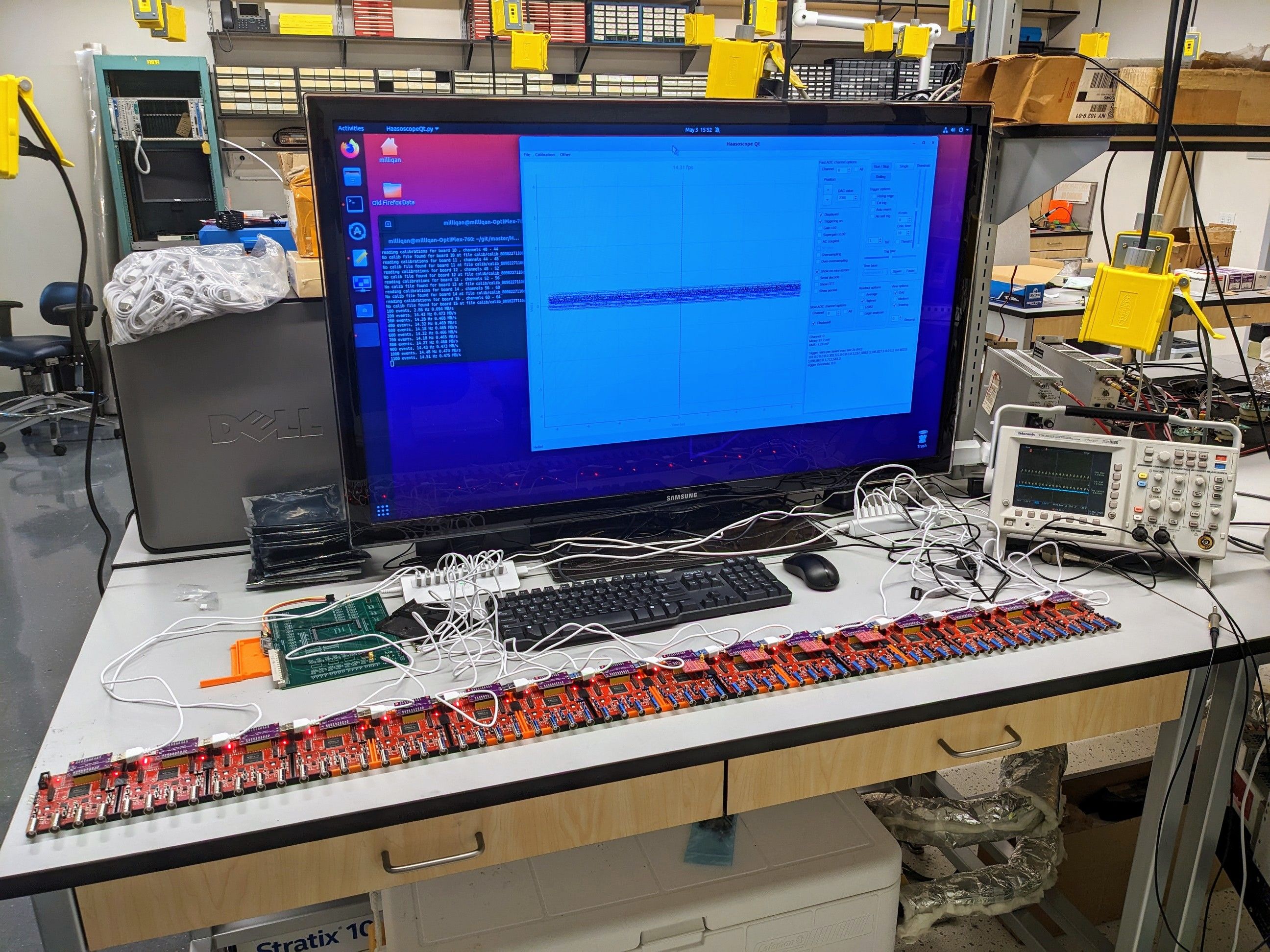
Why a 64-Channel Oscilloscope?
This was for recording data from an experiment at CERN, with many independent particle detectors (photomultiplier tubes), all of which needed to be read out simultaneously to understand what happened in the experiment.
How Synchronization Works
In order to synchronize the boards, three types of signals are used:
Clock Synchronization - They must all share a single clock. This allows each board to record data at the same instant, for instance on the rising edge of the clock signal. The "first" board in the chain generates a master 50 MHz clock signal from its crystal oscillator. This signal is sent to the next board in the chain where it is used as an external clock source. That board then sends that same clock signal to the next board in the chain, etc. Of course, there will be some phase offset of the clock at each board, due to signal delays. These must be calibrated for by applying a single square wave to all boards and then aligning the rising edges from all boards. An automated calibration calculates the phase offsets.
Trigger Propagation - A trigger generated on one board must be propagated to all other boards. When a trigger occurs, it is sent to both the next board forward in the chain and the previous board in the chain, e.g. if board 6 fires, it tells boards 5 and 7. Those two boards then continue the propagation, e.g. to 4 and 8, etc. The propagation ends when the signals reach the first and last boards in the chain.
Board Order Detection - The computer needs to know where each board (each USB2 connection) is in the chain, to know which data corresponds to which channel / input. To determine the order, we first find the one unit which has no good clock coming into it from another board. That must be the first in the chain. Then we attempt to find the next one in the chain, which is the one it’s connected to. We make use of a "spare" signal and set it high on the output of the first in the chain, then see which of the other units sees a high value on their spare input. (All other spare outputs are set low by default.) Once we know the second unit in the chain, we can then find the third in the chain by repeating this trick, etc.
In total that’s 4 signals we need between each pair of boards: a clock, a forward trigger, a backward trigger, and a spare signal. For the original Haasoscope, these signals were simple single-ended pins on headers on the right and left sides of each board. The boards could then be connected together side-by-side. This signaling method had a couple problems. First, it required the boards to be side-by-side. This geometry could get unwieldy for a large number of boards. Maybe you want them stacked a different way, or in a rack, etc. Second, single-ended signals were a bad choice for high-frequency signals, like the 50 MHz clock. High-frequency signals should only be sent on impedance-controlled wires to prevent signal reflections and EM radiation. Those clock signals between the original Haasoscopes radiated like a 50 MHz radio station! It causes noise on the channels.
The Haasoscope Pro Fix: Ethernet-Based Expansion
The original Haasoscope used single-ended pins for these signals, requiring the boards to be side-by-side. This caused issues like geometry constraints and noise interference from high-frequency signals.
The Haasoscope Pro solves this with differential wire pairs—the same principle used in Ethernet cables!
Did you know an Ethernet cable is essentially just four pairs of twisted wires? These are perfect for transmitting our required signals with minimal noise and excellent signal integrity. Here’s a diagram, showing the 4 pairs in different colors:
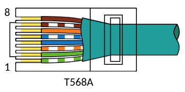
(Technically this is called a RJ45 jack with an 8P8C connector.)
Each of those 4 pairs is a differential pair with a controlled impedance of 100 Ohms. Perfect! The Altera FPGA can easily send and receive data over 100 Ohm differential pairs using the built-in LVDS standard. (We do need an external 100 Ohm resistor as near as possible to each pair at the receiving FPGA.) Just using a single "Ethernet" cable and two "Ethernet" connectors on the back of each Haasoscope Pro, we can transmit all 4 of our required signals between units:
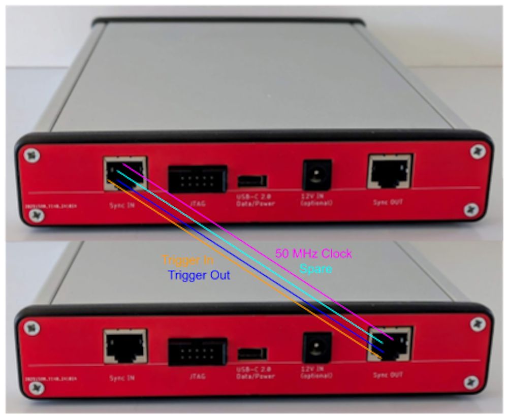
This really adds a lot of flexibility, and has very good signal integrity and EMI performance. You could use a long Ethernet cable to put two Haasoscope Pro’s in different rooms while still acting as one. (No, you can’t propagate the signals through an Ethernet network or LAN or the Internet - remember these are not real Ethernet packets, just LVDS differential pairs.) You could also put many boards in a rack and connect them using cables. Or you could stack them on top of each other, side-by-side, or however you like. Once I get the boards made, I will definitely have to put them all together for a 200 channel GHz oscilloscope! (Is there a world record?)
Bonus: RGB LEDs for Channel Identification
I also added a little RGB LED next to each input BNC. The software can then set the color of that LED to match the color of the channel drawn in the scope GUI on the computer. The LED can also blink when you click on a channel in the GUI to help you find the right one! Why don’t all scopes do that?!
Next Update: Oversampling for Higher Sample Rates
If you’ve been following the Haasoscope Pro story, you know that they also allow another kind of expandability. Two Haasoscope Pro’s can be paired together (in the same way, using an Ethernet cable) to oversample a signal, doubling the effective sample rate to 6.4 GS/s. You just need the additional high-bandwidth analog cable (also available from the campaign page) between the two units. I’ll have details on how that works in a future update!
That’s it for this week. Thanks again for your support! And please don’t hesitate to get in touch via the "Ask a Technical Question" section of the campaign page with your feedback and questions - I really like to get them.
