Music by BUS ERROR Collective, distributed under CC BY-SA 4.0 - find the original here!
Tiliqua’s round screen was inspired by old HP 141S display sections from the 70s. For something bright, low-latency and clear, I eventually settling on a custom 720x720 IPS panel. It is rated at 60 Hz, although in my testing it seems to keep working all the way up to 90 Hz! Anyway, on taking a peek behind Tiliqua’s screen, you’ll see:
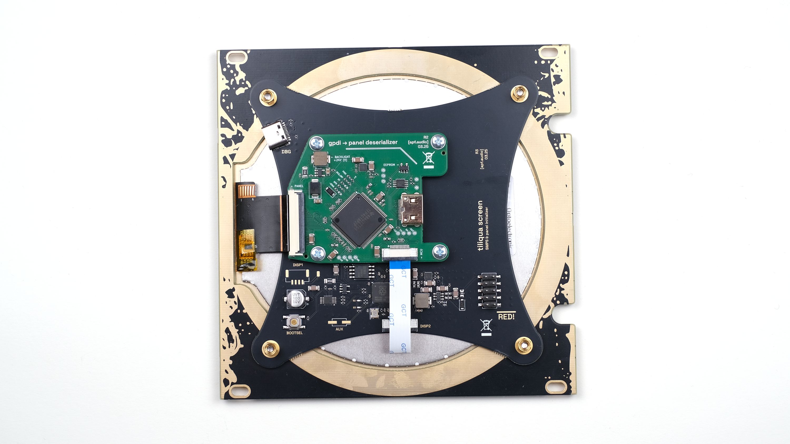
This is the (now third) iteration of the screen’s mechanical stackup. There are four custom PCBAs, two mechanical ones (the outer ring and front panel), as well as two populated PCBAs (one is green here, the production version will be all black):
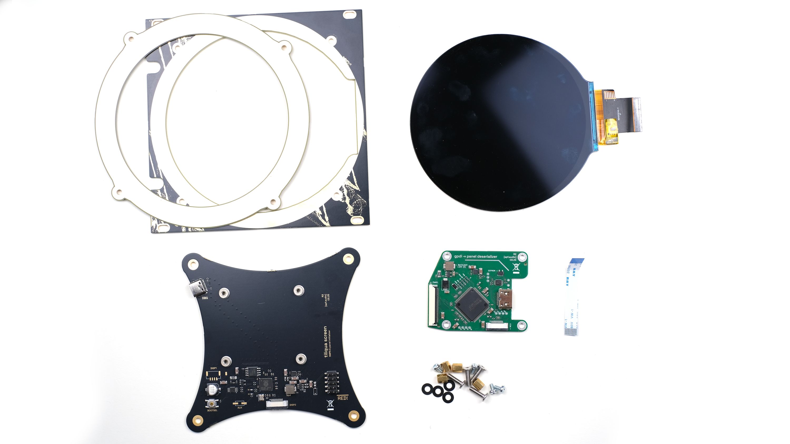
The two interesting PCBAs are the ‘deserializer’ (smaller green one) and ‘backpack’ (larger cross-shaped one).
What Does the Green ‘Deserializer’ PCBA Do?
DVI deserialization: The display panel takes an RGB interface, and this needs to be deserialized (converted) from DVI/TMDS. One reason I went for an RGB interface after trying both MIPI and RGB panels was that often MIPI deserializer chips would take seconds to lock onto a video signal after it was lost. Computer monitors often do this as well. As the video signal is momentarily lost whenever Tiliqua switches bitstreams (and of course whenever the eurorack system is power cycled), a solution that would instantly re-lock was super important. After trying some different deserializers, I eventually settled on the (classic) TFP401 DVI deserializer for this role. This one locks almost instantly!
In fact, the screen locks so fast you can sometimes get one frame to glitch into the next one across a loss of video signal. This looks cool so I’m thinking of keeping it like this, even if it is easy to have clean transitions with a trivial gateware patch…
Timing memory (EDID): Since the display should also work as a standard DVI-compatible monitor (i.e. without Tiliqua), it needs an on-board EEPROM to store the correct display timings. This is also found on the ‘deserializer’ PCBA.
Backlight driver: The panel needs a high-voltage backlight driver, which is also found on this board thanks to a CAT4139.
What Does the Other PCBA Do?
Panel initialization: the IPS panel needs a special sequence of data shifted into it whenever it is powered on, so that its internal controller (NV3052C) interfaces with the panel correctly. This is the role of the RP2040 microcontroller, which performs this initialization sequence whenever it boots up.
Panel watchdog: in rare cases (for example, invalid video signals) I have found that it is possible for the panel controller to lock up. The RP2040 is able to detect this and reset the panel in two ways: using the panel’s reset line, and by power cycling the entire deserializer PCBA. This means it’s not possible to lock up the panel even with dodgy or unreliable gateware (which could totally happen on this experimental platform!)
Power supply: The display and backlight draw quite some power, so to keep things cool there’s a switchmode power supply built into the ‘backpack’ PCBA.
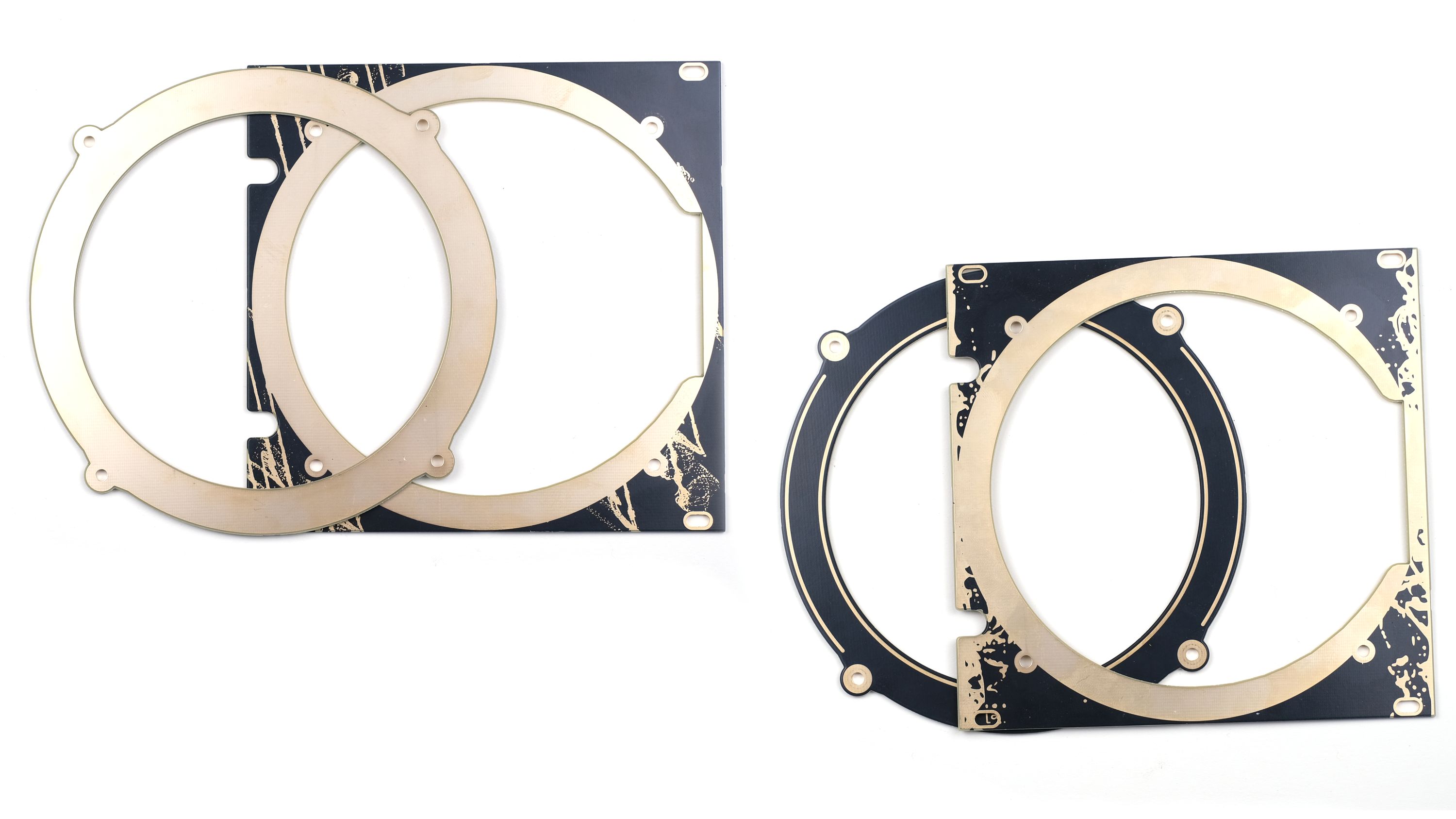
Reversible Panels
Just for fun, I put different graphics on the front and back of the mechanical panels, so you can flip them over if you want a different design:
That’s It!
We hope you now have a better idea of what’s going on inside Tiliqua’s round screen. If you have questions of any kind about Tiliqua, feel free to contact us by email, using the "Ask a question" link on our campaign page, or on Matrix. Until next week!