Project update 10 of 16
Ready for Production!
by Robert JProduction Getting Started
Over the past few weeks, we’ve been working hard to verify the prototype boards we received at the end of the campaign. We’re happy to say that we have now ironed out all remaining issues with the prototypes. We have a design we are truly proud of and we cannot wait to get into your hands.
Next week, we will be able to send the final design files to our trusted contract manufacturer who have already gathered all necessary materials for our first production run of 1000 units.
From Final Prototype to Production-Ready Design
It has taken us many design revisions to reach the finishing line but we’re finally there! With our penultimate design we were very close and there were no major issues to resolve layout-wise. The majority of the issues we had to address with these protos were to do with subtle mechanical properties of the components we had selected in the BOM.
Getting the Button Right
Gliss features a bi-coloured illuminated button which is an integral part of the module’s minimal user interface. We wanted to make sure that the button had just the right feel and was high quality, while sitting at an ergonomic height from the faceplate.
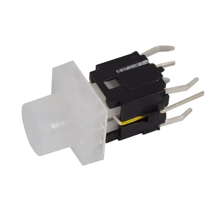
The first button we used was 5GTH93561, we weren’t satisfied with the click which was too loud, and the tactile feeling wasn’t quite right for our purposes. The second button we selected HIGHLY PB6149L-13 was much better, but its cap protruded 5 mm from the faceplate, which was not aesthetically pleasing. We finally settled on the PB01-109TL which has a low profile cap which protrudes just a couple of mm from the faceplate – perfection.
Headers and Sockets
While evaluating the penultimate prototypes, we also realised that there was a 0.5 mm difference in inter-board spacing at the top of the module and the bottom. Gliss is made up of three boards, and their accurate positioning is very important for the correct functioning of the module. The distance between the microcontroller board and faceplate needs to be exact, to ensure the nuts can be screwed on the jack and the button is not impeded. At the same time, the distance between the LED board and the faceplate determines the amount of diffraction of the LED light in the FR4 of the faceplate, so that can change the visual appearance of the module significantly.
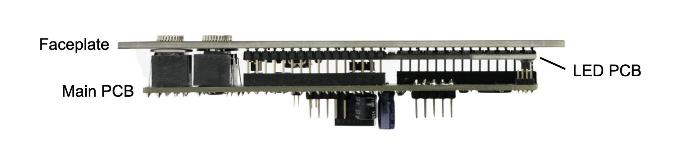
The slight difference in inter-board spacing at the top and bottom was caused by the pairing of SMD header pins and sockets we had chosen to connect the faceplate and main PCB. Our options were limited to the standard sizes our contract manufacturer could get their hands on. We initially investigated different options with spacers or washers, but they all seemed a bit too much of a hack. Instead, thanks to the larger than expected number of backers we received during the campaign, we have been able to resolve this issue by getting a custom header made especially for this module, which allows us to guarantee that the spacing is exactly the size we want it to be. Thanks to you, our backers, we have been able to meet the minimum order quantities for getting these custom headers designed and manufactured.
Dual Colour Soldermask
In the previous round of prototypes, the faceplate featured black soldermask, with the touch sensor made from exposed copper pads with ENIG finish. Although we loved the look of the ENIG finish, we were concerned that with extensive use over the years, the exposed material would tarnish and lose its shine. We corresponded with our contract manufacturer and decided that we could instead use dual soldermasks on the faceplate: black as before, and transparent over the touch sensor. This is a custom process, which can be costly for small quantities of boards, but quickly pays off when making larger numbers.
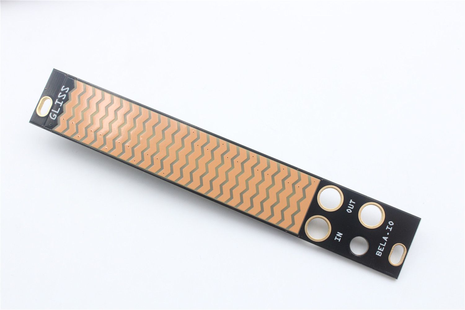
An additional advantage of the transparent soldermask covering the copper pads of the sensor is that protection against electrostatic discharge (ESD) is now provided by the soldermask, so we can safely remove the ESD protection diodes that we previously had on all exposed pads. Thanks to this, the dual-color soldermask provides a net saving in our costs per-faceplate, which is how we have been able to go the extra mile and ship the module to all our backers with two faceplates, without increasing our costs too much.
Vertical QWIIC Connectors Stress Testing
We have also been putting the final prototypes of the Trill sensors through their paces. We quickly verified that the new designs were working as expected, and we were very happy with the performance and look of them. However, after repeatedly plugging and unplugging the QWIIC cables into the vertical QWIIC connector on the back of the sensors, we realised that these connectors were not as sturdy as we would have liked.
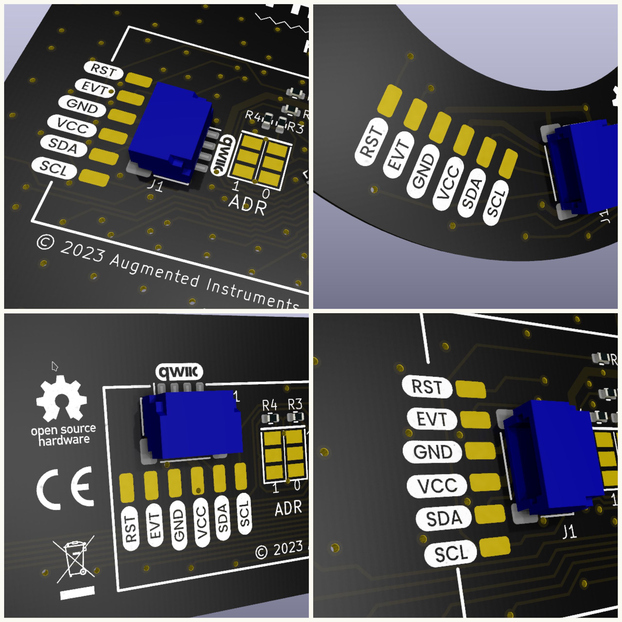
When applying a relative amount of force in the direction of the pins, it was possible to shear the connector from the board, ripping it off with some traces attached. This issue only affects the vertical QWIIC connectors, and the risk of ripping the connector off is higher when plugging and unplugging the QWIIC cable frequently and carelessly. For this reason, we decided to go with a horizontal QWIIC connector instead on all Trill sensors, aside from the Trill Hub. This connector is much more resilient to stresses put on it when pulling cables carelessly. This also means that we shave a couple of millimeters off the minimum vertical space needed to mount the Trill sensors, good news for those of you who want to create super thin (under 10 mm) instruments and interfaces.
Promotional Units Going Out Next Week
In other news, we have a handful of promotional units going to an exciting selection of artists and synthesizer experts, so keep an eye on our social media channels for updates about that in the coming weeks.
Delivery Date Update
With production almost underway, the machine for getting these modules to you is now fully in motion. The fine tuning of the BOM and fabrication of custom headers has set us back a little bit, but we hope that it will only be a couple of weeks, and no longer than a month with respect to the original delivery date of May 1st.
We can’t wait to get these modules out to you!