Project update 3 of 6
Colorways and PCB Design
As we approach the campaign funding goal, it is time for a new update. We wanted to show you what LED colors look like and talk about reducing the size of PCB by placing components on the back side.
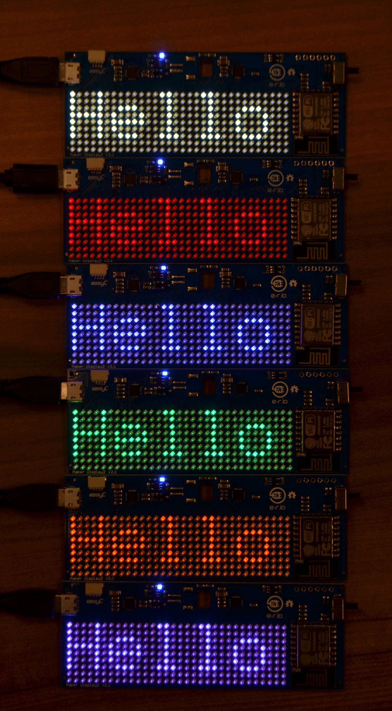
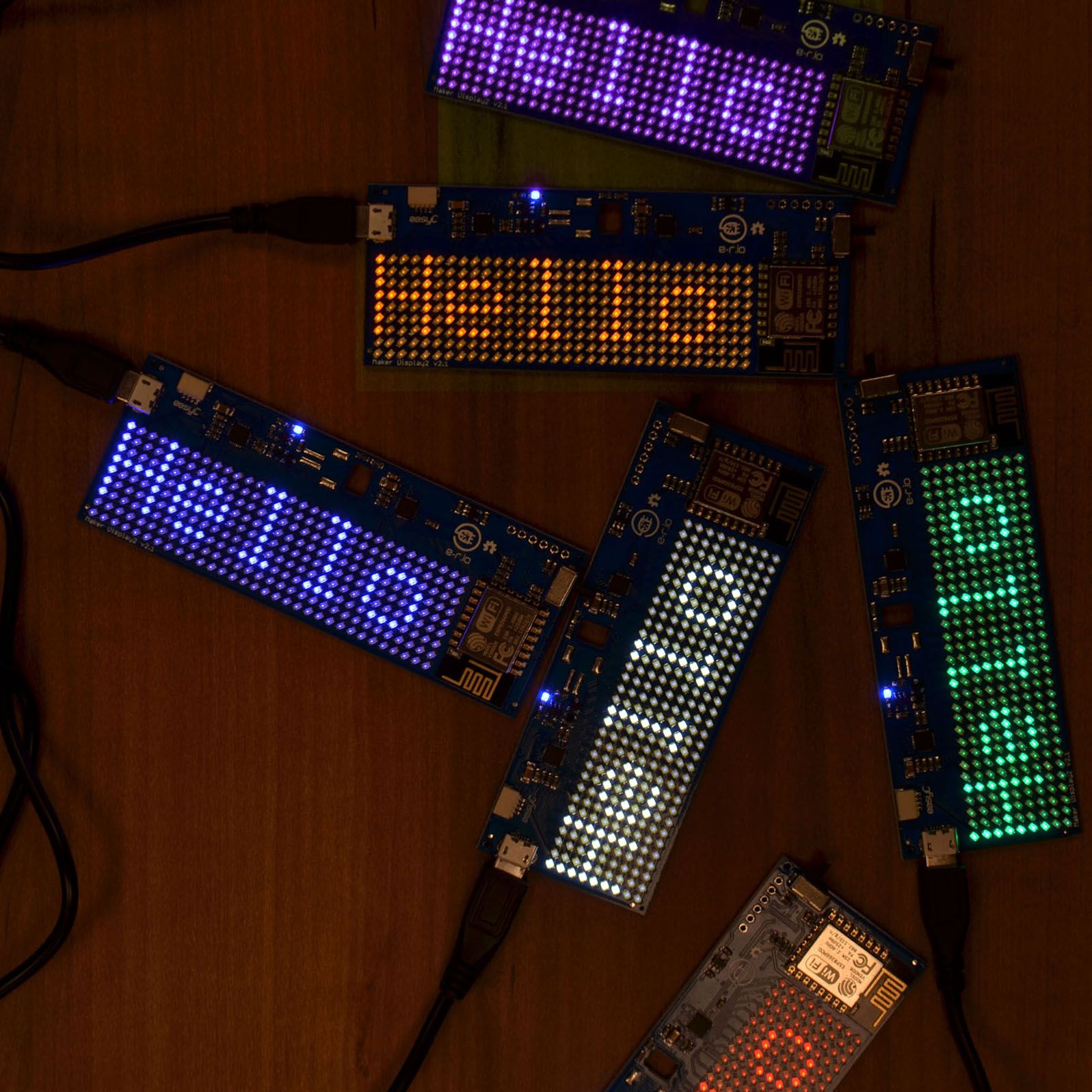
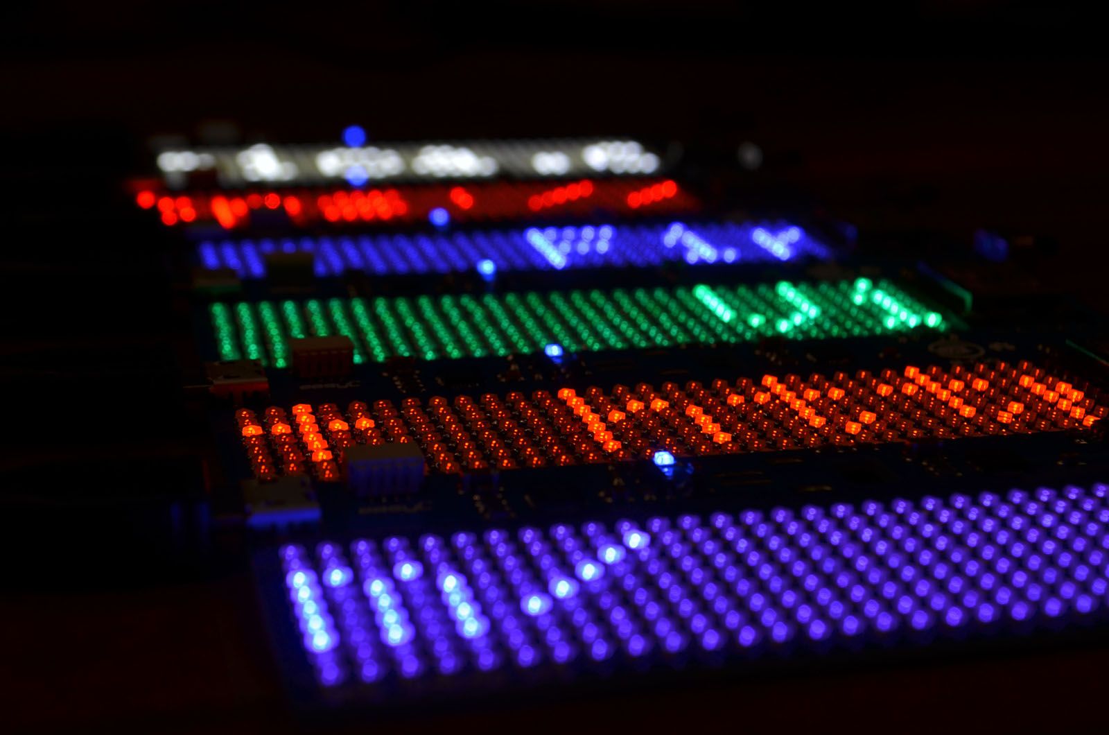
You have probably noticed that we haven’t put a photo of all displays being turned on to the campaign page yet. That’s because we didn’t have the chance to lay our Pick and Place heads on some purple LEDs. We have finally gotten them last Friday and made a few displays over the weekend. Check out these pictures of all displays turned on:
The question we encounter quite often is: “Is it possible to put electronics
on another side of the PCB?”. It is a very good question, if it were done,
it would result in a PCB which has LED matrix on one side and electronics
on the other, meaning that PCB would be of minimal size, restricted only by
LED matrix size. The PCB edges would be minimal as well, so placing the board
in some kind of housing would be better looking, as well. So, why haven’t we done
that in the first place?
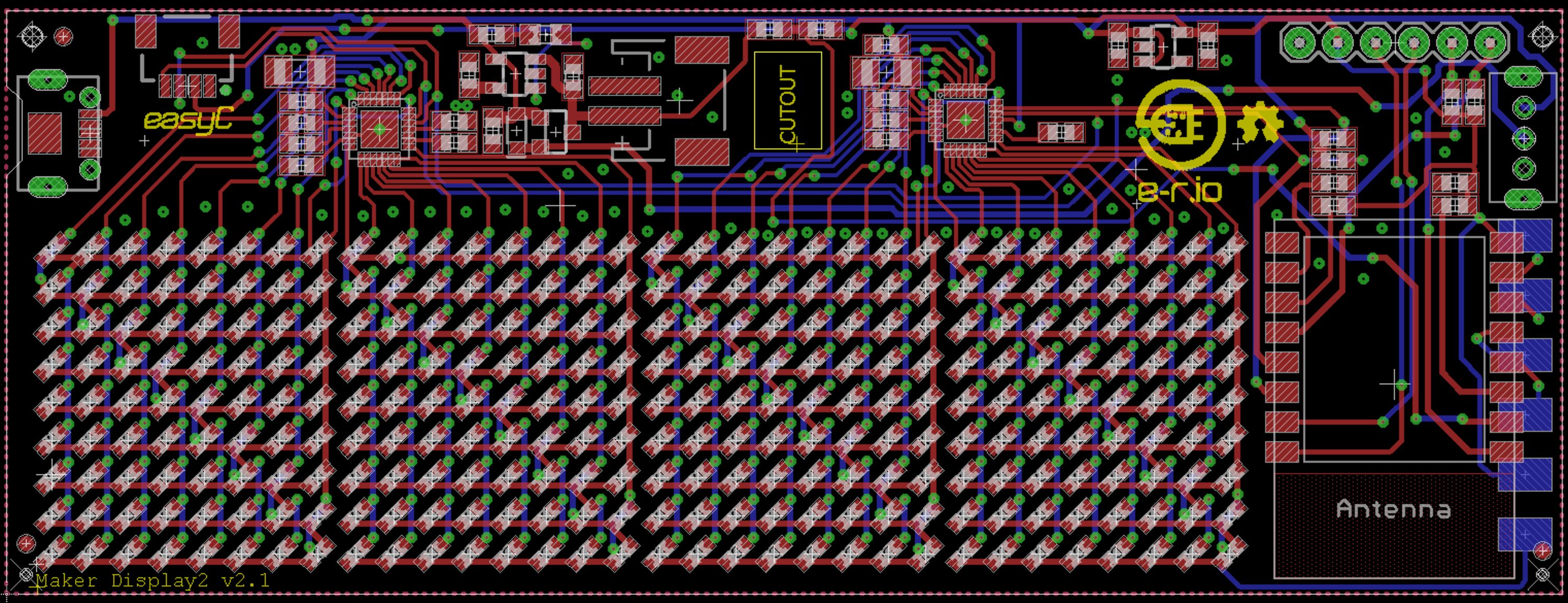
This picture is a screenshot from Eagle, software used to design PCBs. The red color
represents top copper layer, while blue shows bottom copper layer. The PCB is 2-layer,
so each layer will go to one side of the PCB. Those small green circles are vias, which
are used to connect top and bottom layer traces. Since matrix of LEDs is connected in a
special way, many of these traces intersect and are connected using vias. Because of that,
most of the space behind the LEDs is occupied with vias and bottom layer traces.
Now, look
for two squares which are the driver chips at the upper part of PCB. Traces coming out of
them are really dense. We wanted to put them behind the LED matrix, but it was not really
possible - they would collide with vias and that must not happen. Because of this, we decided
to put electronics to the top and right side of the matrix.
Since there is a huge interest to get these parts to the back side of the PCB, we reevaluated the problem and came up with a solution. We would make two PCBs: one with LEDs and one with all the electronics. They would be soldered one to another on the back side with solder pads, making a sandwich of PCBs. We will not use headers in order to minimize total height of the PCB sandwich. Most importantly, LED matrix would only take up space that it actually needs.
This new solution will be made as version 2 and will be offered additionally, after all units from this campaign are shipped. All crowdfunding units will be shipped as current version (1). If you want to wait for next version, please make a note when ordering. We expect to have version 2 ready for shipping in July.