Project update 7 of 20
Stretch Goals and Survey Results
Thanks to all of you who filled out our survey for potential stretch goals. In this update, we go over the results and lay out our plans for stretch goals.
First, let’s just say the survey comment "give me knobs, or give me death” left an impression and made us realize that adding an encoder knob could be a life saver in some cases. :)
As a reminder, the survey asked how excited you were on a scale of zero to six about the following features:
- USB Isolation and USB + Ethernet Protections
- SD card
- Encoder Knob
- Larger, More Powerful Display
- Third Channel
- Two current ranges (0-500 mA and 0-5 A)
- Breakout Board
In addition, there was a free-form comment section.
And the Winners Are…
The top-ranked feature was the Encoder Knob. Tied for second place were USB Isolation and USB + Ethernet Protections and Third Channel.
Stretch Goals
The survey results definitely helped us to decide what our stretch goals should be. Of course, we also had to consider other factors, like cost, feasibility, and logistical complexity. After all that, we came up with this official list of stretch goals:
| Stretch Goal | Unlock Amount | Feature Set |
|---|---|---|
| Encoder Knob | $55,000 | Arduino shield with built in encoder and modified front panel |
| USB Isolation and More | $60,000 | AUX PS module populated with USB isolator and com ports ESD protections, one MCU-operated power relay (e.g., 230 VAC / 8 A), modified rear panel, and 4 GB SD card |
| Dual Current Range | $88,000 | Improved power boards with dual current range (0-500 mA / 0-5 A) |
For a given stretch goal, if we end up raising more than the stretch goal’s unlock amount, then that stretch goal’s feature set is automatically added to everyone’s order at no additional cost. Stretch goals are cumulative. For example, if we end up raising $75,000, then both the "Encoder Knob" and "USB Isolation and More" features are added to the EEZ H24005 for everyone to enjoy. One important note: stretch goals will be determined by the amount raised during the campaign itself, which ends on February 23, 2017, not by any amount raised during the pre-order period after the campaign has ended.
If we raise more than our top stretch goal ($88,000), then we’ll put our thinking caps back on and start coming up with even grander stretch goals.
Encoder Knob!
Yes, we realize the first stretch goal is only a few orders away from being unlocked. We’ve already started work to make it happen - expect some firmware updates soon.
In addition to firmware, the encoder requires revision of the front panel and Arduino Shield PCB. All backers who have already pledged for only the Enclosure and Assemblies will be contacted in case they’ve already made their own set of PCBs (using one of the previous revisions available on GitHub) so we can include in their shipments one free Arduino Shield bare PCB.
Resolution and Noise
We learned from your comments many other things that we’ll take into consideration in the future, such as the fact higher resolution and lower noise are always more then welcome. We already tried to address that within the limits of our expertise and budget. Better resolution (i.e., 1 mV/mA) was intentionally not “advertised” but it should be easily achievable thanks to the ADC and DAC we use. The most recent firmware revision also “knows” how to manage 10 m or 1 m resolution. Basically, we just need more time for testing this.
Better voltage resolution can be expected also thanks to the remote sensing feature. We’ll show off this feature in one the upcoming demo videos. For better current resolution (some of you proposed even 100 uA or better to measure/limit connected load stand-by consumption) we’ll need at least two current ranges, which is why the dual current range was an option in the survey and is now a stretch goal.
Regarding noise, we tried to silence the power pre-regulator as much as possible, even going so far as to switch it off (the so-called “low ripple” mode of operation). Hopefully, the current design will satisfy most of your practical needs. It seems that such topics tend to start heated discussion that end up comparing apples to oranges (different probing method, class of instruments, area of usage/requirements, etc). We’ll prepare another video to address this topic.
Front Panel Features
The following three features can be found in many of your comments: mechanical switches for output enable, output terminals, and a MCU-controlled relay.
The first one looks straightforward as long as we still have a couple of spare MCU pins to connect switches. Unfortunately with the current design where the PCB (Arduino Shield) is directly mounted on the rear side of the enclosure front panel that is simply impossible because there is no space left on the PCB. But we tried to compensate for this by providing a huge area on the main page on the touch-screen that acts as an output enable switch. Additionally, a power switch is added on the front panel to shut down both channels immediately in case of emergency.
One possibility is to place two switches on the left side of the TFT display where they would be “out of symmetry” with the channels’ other specific parts, such as LEDs, push-in connectors, and output terminals. If we decide to add those two switches then a power switch doesn’t make a lot of sense because AC inlets come with a robust switch.
High quality output terminals are a concern for many people, and for good reason: they have to endure many insertions/removals and mechanical stress, sparks, etc. The currently selected terminals feel robust, but we have not a chance to test it over a prolonged period of time. And yes, we are using standard 19.05 mm spacing so a BNC adapter, for example, can be smoothly inserted. But, quality and spacing are not all that people mentioned. Terminal type seems as an important issue for many people: as they prefer more shrouded banana plugs, or screw type terminals. We hope it’s obvious we cannot support all three (or more?) types of terminals on the front panel. One possibility is to provide rear panel terminals but we are not sure we can easily add it with the current wiring constellation (and we are trying to reduce wiring to the maximum possible extent).
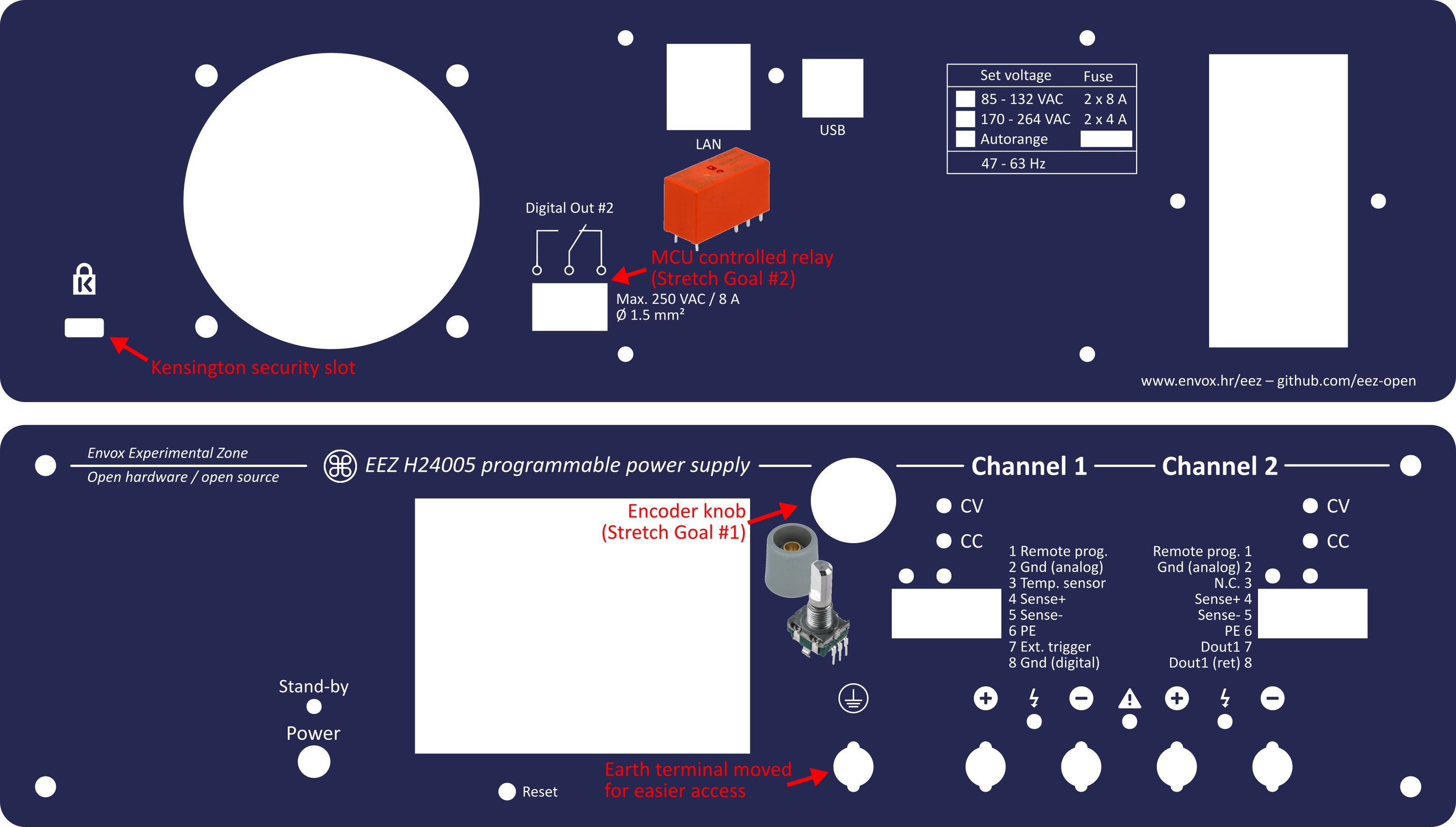
The third option is already addressed to some extend: we exposed one opto-isolated digital output on the front panel. Adding a relay will require modifying the Arduino Shield if we want to expose its terminals on the front panel or modifying the AUX PS module for terminals on the rear panel. We can follow the latter proposal if the second stretch goal (USB Isolation and More) is reached.
Give Me More Power
The survey also taught us that the more power, the better. We’d like to remind you that two channels can be coupled safely in series or parallel under MCU supervision. That changes the EEZ H24005 into a single channel unit with up to 80 V or 10 A (maximum 310 W). Furthermore, hack #1 is intended for people who are interesting to use their own transformer instead of the included AC/DC modules.
Connectivity with the External World and More Instruments
Finally, we can say many of you want to see a sort of external management console in cases where multiple power supplies are deployed. A complete infrastructure exists on the firmware side and without extra effort one could start to do that from day one using the SCPI command set to remotely set output values, lock/unlock or power-up/shut down units, collect measured output values, and many more things.
Finally we’d like to thank you for all mentioning other test and measurement instruments you’d like to see integrated with the EEZ H24005, such as electronic load, waveform generator, and 2- or 4-quadrant power supply. That’s exactly what the EEZ Open initiative is all about: offering various T&M solutions that go beyond DIY/hobbist projects and compete with commercial devices, but with free and open software and hardware design.