Project update 4 of 9
Four Prototypes: The Evolution of SPIDriver
Often the finished product gets all the attention, but as makers we know that the journey there can be quite long.
Make something.
Think about it.
Then make something better.
This post is about that process.
The Beginning
When finishing Gameduino 1 about seven years ago, I wanted to run tests on the real hardware. This is the particular idea — just driving a SPI device from the PC. A tiny microcontroller isn’t the best programming environment, and that’s always going to be true. Some microcontrollers have better development environments than others, but the fact is that the resources of our development machines are huge by comparison. So how to get a PC talking SPI? Clearly the PC can talk to an Arduino over the serial connection, then the Arduino can talk SPI. This was the beginning. A little bit of Arduino code turned it into a UART/SPI bridge, then some Python on the PC talked to the Arduino.
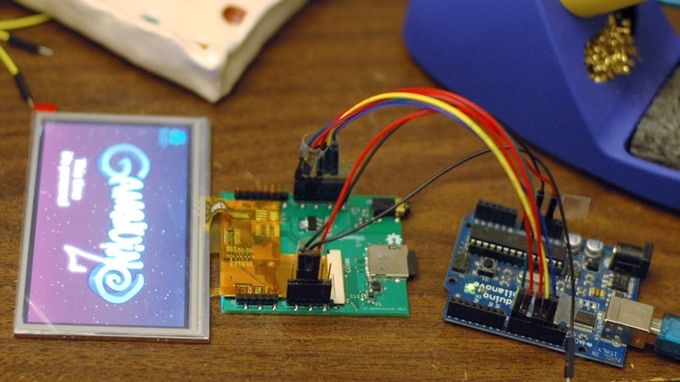
It worked fine, but was not especially elegant.
It also only lasted until the Arduino was scavenged for another project.
On a Breadboard
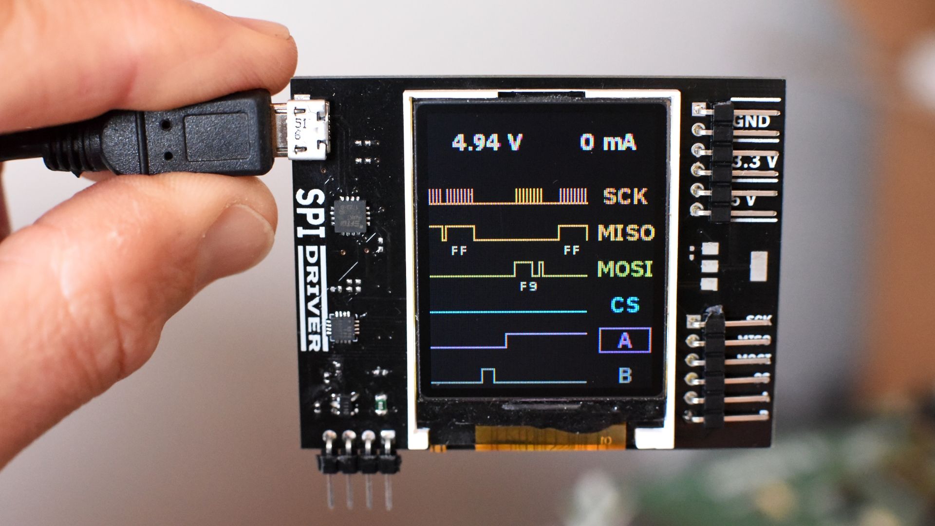
In late 2017, I started to look at small LCD panels, paired with tiny 8-bit microcontrollers. The hardware would be inexpensive, but with carefully written firmware the final image could look quite nice. An obvious application was the UART/SPI bridge that I use every day. Wouldn’t it be great if instead of a single flickering LED it had a proper scope-style display? Then you could know what it was doing just by looking at it.
With a few components from Adafruit, it was fairly straightforward to get test images on a real display. This is the first image:
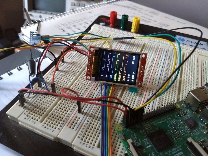
The text is drawn in a nice anti-aliased font. The on-screen signal colors are chosen to match the colors of the jumpers. It looked kind of neat, so I decided to go ahead with a prototype.
First Prototype PCB
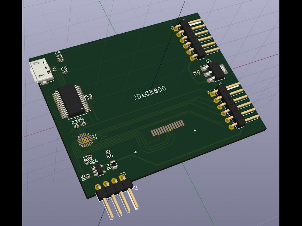
The PCB layout was done in KiCAD, having first made the netlist in David Vandenbout’s SKiDL. (That’s right — SPIDriver has never existed as a schematic!). The board done, I sent it out to OSH Park and a week later had three purple proto boards ready for assembly.
This was a hand-solder, and here are two of the boards. A habit I picked up from my days bringing up GPUs: keep toe tags on prototypes so you know which one they are!
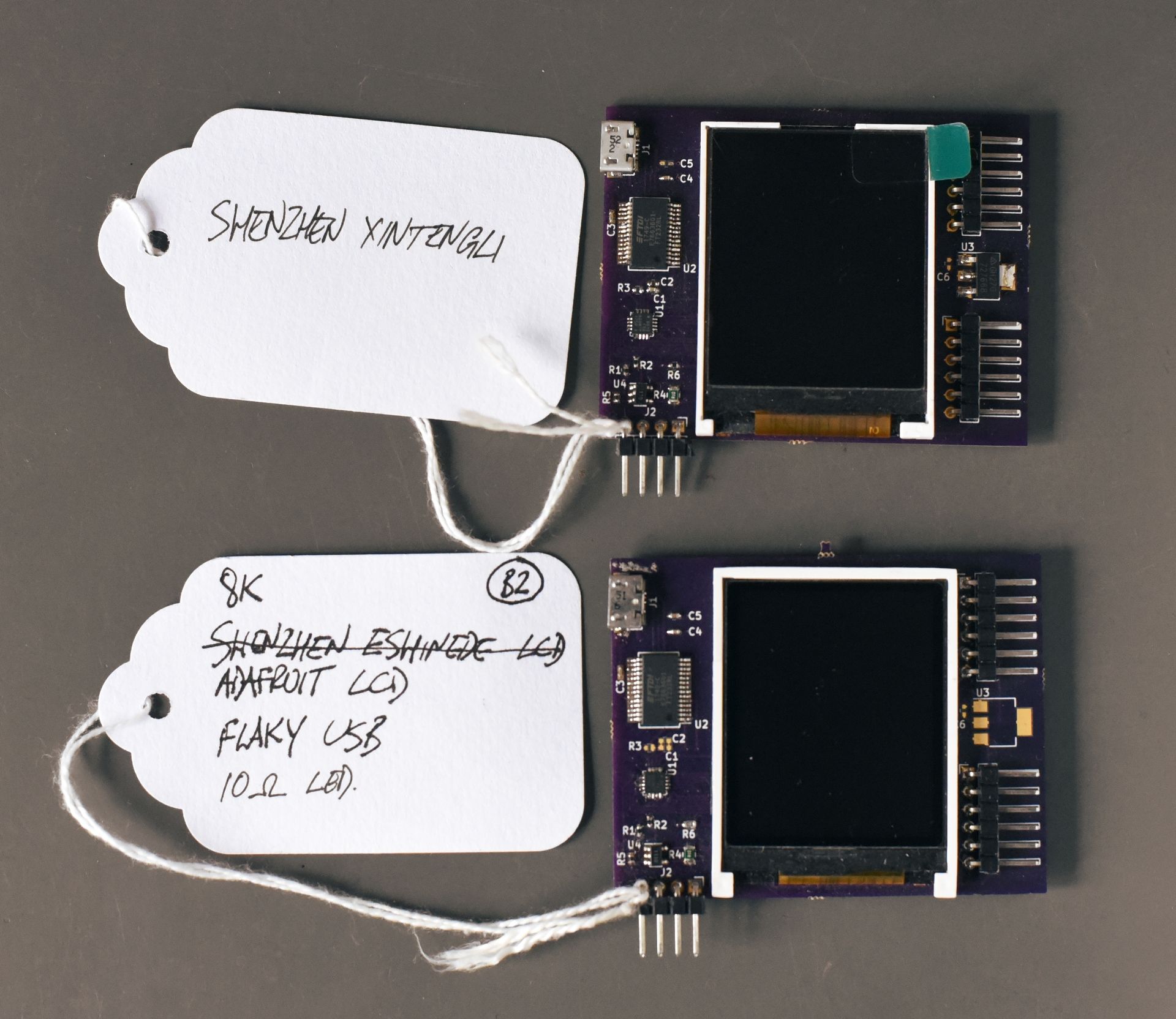
I considered these the first "real" prototypes, and wrote most of the firmware on them. The top-left chip is a FTDI FT232R - as used in many OSHW designs. I assumed it’s the cheapest FTDI UART, so designed it straight in. But when I actually checked prices, I found that the newer FT230X is significantly cheaper. Time for a new version.
Better Prototype PCB
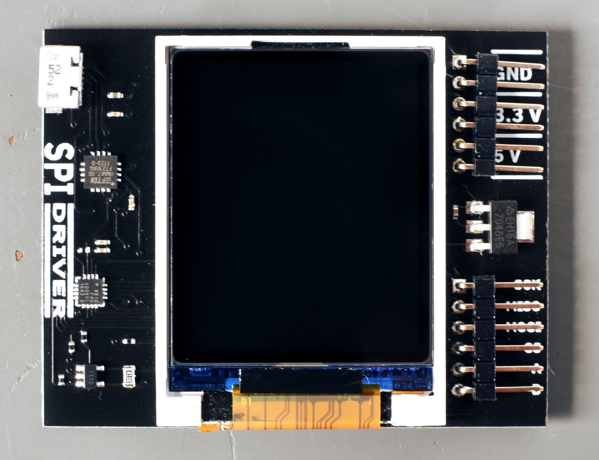
The next iteration was a run of 20 boards, with the updated USB UART, in black, with a solder stencil so I could stop hand-soldering microscopic components.
This is the prototype that appears in all the Crowd Supply images. You can see a programming connector, bottom left. Apart from that it is like the final version.
Final Version
This is the final prototype before production. The programming connector is gone, replaced by pogo pads on the back of the PCB.
If you’re backing SPIDriver, you’ll be receiving one very much like this in a few weeks.