Project update 19 of 36
RF Performance in the HF Band
TL;DR:
- We've received so many questions about the **HF band and RF performance
below 30 MHz, that we decided to do a special update about this. Our tests show that it is indeed possible to use XTRX in the HF band but this requires a good antenna and an external filter. 2. While working on the HF band support we decided to make XTRX even more versatile and added one more FPC header with direct access to LMS7002M ADCs** which can be used for the HF band direct sampling or to make 4-channel oscilloscope. 3. Another bit of good news: we’ve added support for a great tool — SDRangel. Currently, it only works with a single channel (XTRX has two) and can do RX only but we already use it for testing and awesome demos.
Read on for details.
RF Performance in the HF Band
As requested by many of you we measured the RF matching and degradation of lower bands with the help of an RF signal generator and SDRangel’s great visualization. Here’s what we’ve got when sweeping a constant amplitude sine wave from 0.5 MHz to 17 MHz:
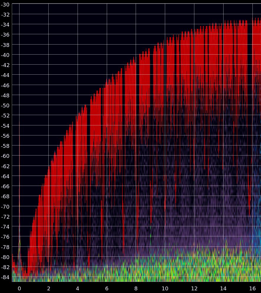
The gaps you can see in the curve can be ignored. They appear at random places and move from sweep to sweep are because the XTRX and the generator are not synchronized. We only show frequencies below 15 MHz because everything above 15 MHz is flat until we hit much higher frequencies which is a topic for another measurement. We had previously estimated -3 dB attenuation at 10 MHz but it reality it seems to be at around 11 MHz, so we were pretty close. Here are the tabulated attentuation levels:
| MHz | Attenuation |
|---|---|
| 15 | ~0 dB |
| 14 | 1 dB |
| 13 | 1 dB |
| 12 | 2 dB |
| 11 | 3 dB |
| 10 | 4 dB |
| 9 | 5 dB |
| 8 | 7 dB |
| 7 | 10 dB |
| 6 | 13 dB |
| 5 | 15 dB |
| 4 | 19 dB |
| 3 | 23 dB |
| 2 | 29 dB |
| 1 | 40 dB |
| 0.5 | 49 dB |
After these measurements, we reviewed our design again to see what we could do to improve HF performance. Unfortunately, it seems there is no easy fix. To significantly improve low-frequency bands, we need to replace the RF switch and the matching balun. With the space constraints we face at XTRX, we just can’t find a good alternative to the ones we already have. Keeping things tiny is always challenging.
This brings up a question — is it even possible for XTRX to receive HF radio? Frequencies below 30 MHz are tricky to handle with the LMS7002M RFIC. The minimum LO frequency of LMS7002M is 30 MHz and the only possible way to get below 30 MHz is to capture the whole band and then filter desired frequencies in the digital domain. The idea is illustrated below:
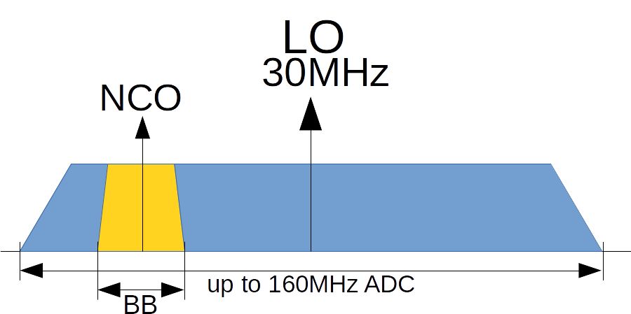
The LMS7002 works at the fixed (minimum) LO of 30 MHz. We then use a digital mixer (aka numerically-controlled oscillator or NCO) built into the LMS7002 to move the baseband (center) frequency of the received signal to the desired frequency. Since we don’t need the entire bandwidth of the ADC, we use built-in decimators (up to 64) to get lower baseband (BB) bandwidth.
As an example, if we set the ADC (IF) bandwidth to 48 MHz, and set the NCO to -13 MHz we will get a 7 MHz center frequency. With 64x decimation, we will end up with 750 kHz of the signal originally centered at the 7 MHz. The main disadvantage of this method is that we are capturing a really wide spectrum at the ADC (6 MHz - 54 MHz in our example) and any strong signal in the band will saturate it. Which means we can’t use the low-noise amplifier (LNA) to improve reception at these low frequencies.
To validate the theory, we tried to receive something around the 49-meter band (5.8 – 6.2 MHz) — it is a point with moderate attenuation, which means it can actually work. To get down to these frequencies with an LMS7002, a minimum of 2 * (30-6) = 48 MHz RF bandwidth is required. Which means that we’re sampling everything from 6 MHz to 54 MHz which partially covers the analog TV band which has a lot of extremely strong signals in our region. As a good practice, all RX gains have to be set to minimum (zero) in such conditions. Initially, we used a long single wire antenna with no filtering which only gave us a lot of noise and no useful signals. We have never worked with HF, so we didn’t have filers for this band and Andrey had to quickly put together a 20 MHz low-pass filter (we selected 20 MHz to be able to experiment with other HF bands, too):
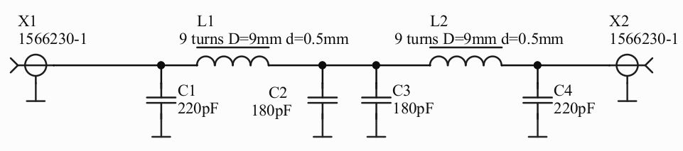
Using plain FTP Ethernet cable wires for the coils, and a spare PCB for the assembly, we came up with this:
We put it in an aluminum box and, using a signal analyzer and tracking generator, Andrey measured it:
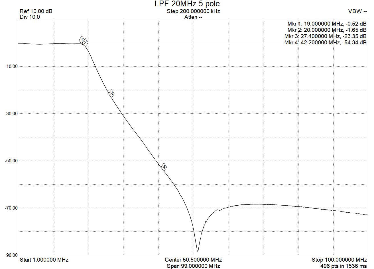
Not a bad result for 5-10 minutes of work. I (Sergey) tested again and it was much better, there was definitely less noise; however, I didn’t see any broadcasting. The last time I did something with lower frequencies was back in school when I was making a crystal radio and I remember that the important part was the antenna. I searched for HF antenna designs and settled with a rectangle loop antenna. Leaving in an apartment it’s not really possible to place it outside, so I temporarily installed it inside my apartment’s hallway while the rest of my family were asleep and couldn’t complain. It was roughly 1.5 m by 3.5 m and was made from an Ethernet cable’s twisted pairs with a coat hanger as a mast on one side and a kitchen furniture at the other. Obviously not the best design ever, it was still far better than the original single wire. Turning on XTRX and looking for radio stations was a success:
So, long story short, it’s quite possible to use XTRX as an HF receiver :) A proper antenna is the key. When you go down to about 6 MHz, the ADC is covering a lot of spectrum, so an external filter is also strongly advised.
This might work for some of you and might not work for others. But at least now you know what exactly to expect.
Direct Access to LMS7002M ADCs
We’ve received a lot of requests for improving the HF band and this made us think what else can we do. 80 MSPS ADC built into LMS7002M we can cover the whole HF band with direct sampling. So we’ve introduced one more FPC cable header on the XTRX — marked with the red outline on the picture below:
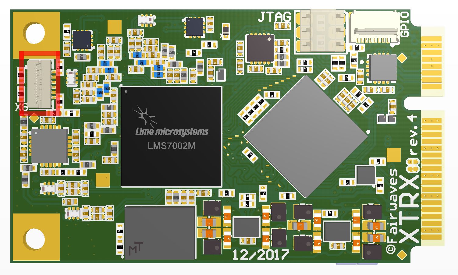
This new header provides direct access to all four LMS7002’s ADCs (2 channels, I and Q each):
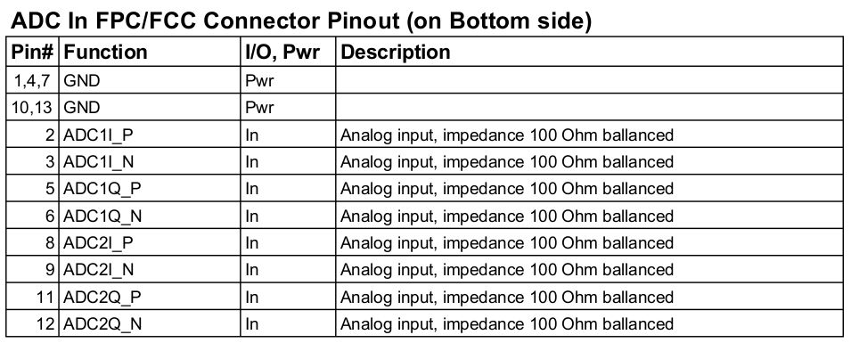
This connector can be used for making a two-channel quadrature frontend or a four-channel direct conversion one. One even can implement a four-channel oscilloscope board. Each ADC is up to 80 MSPS.
We don’t have specific boards for direct connection to ADCs in mind yet, so please share what’s interesting to you.
Thanks for your attention and stay tuned for more updates.