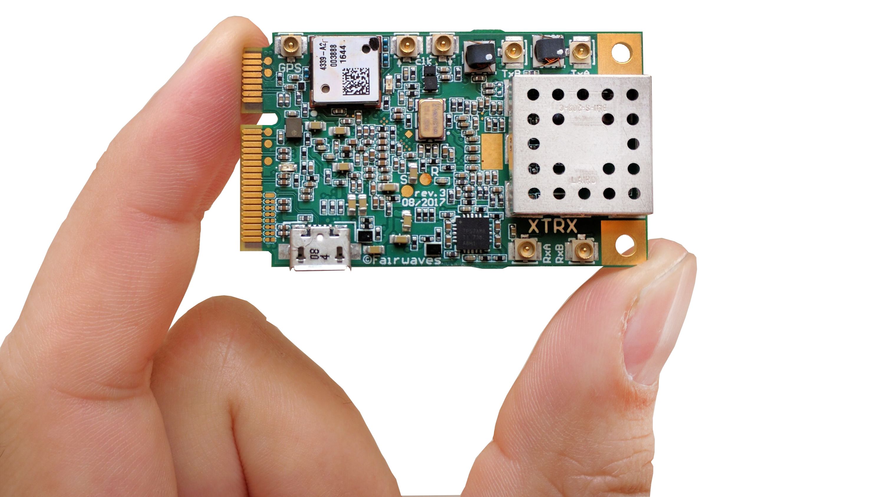
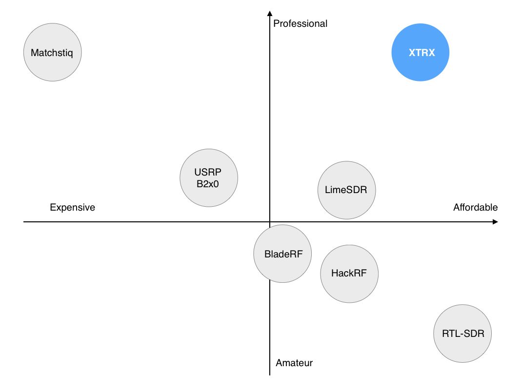
XTRX is the smallest, easily embeddable software-defined radio (SDR). It is both affordable and high-performance. Its professional-grade, drop-in technology is designed to enable the next generation of wireless solutions, from prototype to production.
While LTE modems and GPS receivers are commodity parts easily bought from your favorite electronic components store and added to your project, in order to embed an SDR you would have to spend precious time and money on a custom design — until now. With XTRX, you can easily embed an SDR and stay focused on what your customers really need.
XTRX is the best platform available today for building SDR-based products. We designed it specifically for demanding embedded applications:
XTRX isn’t for everyone. We expect most people interested in XTRX to already have some experience with SDRs. If you’ve never used an SDR before, XTRX might be a bit overwhelming for you. XTRX might be right for you if you have:
If this describes you, or you are looking for a better SDR, fear not and read on!
Here are just a few of the things you could use XTRX for:
XTRX boards can share the same sampling and reference clocks, which makes it easy to build a massive multiple input, multiple output (MIMO) system.
With synchronized clocks, multiple XTRX boards can collectively monitor very large chunks of the RF spectrum. For example, eight synchronized XTRX boards could monitor nearly 1 GHz of bandwidth.
The combination of XTRX’s accurate, stable clock, on-board GPSDO, and low-latency PCIe bus makes LTE possible out of the box.
When inserted into a Mini PCIe slot reserved for cellular modems, XTRX appears as a USB SIM card reader.
Power consumption, weight, size, and performance all matter when it comes to drones and embedded systems. XTRX’s Mini PCIe form factor and GPIO enable you to interface with a wide variety of single board computers, sensors, and actuators.
You can use the FPGA to accelerate your real-time signal processing; the high-speed, low-latency PCIe bus allows shuttling data back and forth between the host CPU and XTRX’s FPGA.
If you have in mind specific applications for XTRX, we’d love to hear from you. Tell us about your project by filling out our survey, and we’ll consider giving you a free XTRX revision 3 board before the revision 4 boards are made.
We’re publishig all XTRX-related code under the xtrx-sdr GitHub organization. Here are the most important repositories to note:
| USRP B2x0 | bladeRF | LimeSDR | LimeSDR Mini | RTL-SDR | XTRX | |
|---|---|---|---|---|---|---|
| Tuning range | 70 MHz - 6 GHz | 300 MHz - 3.8 GHz | 30 MHz - 3.8 GHz | 10 MHz - 3.5 GHz | 22 MHz - 2.2 GHz | 30 MHz - 3.7 GHz |
| Duplex | Full MIMO | Full SISO | Full MIMO | Full SISO | RX only | Full MIMO |
| Max sampling rate | 61.44 MSPS | 40 MSPS | 61.44 MSPS | 30.72 MSPS | 3.2 MSPS | 120 MSPS SISO / 90 MSPS MIMO |
| ADC/DAC resolution | 12-bit | 12-bit | 12-bit | 12-bit | 8-bit | 12-bit |
| Max RF bandwidth | 56 MHz | 28 MHz | 61.44 MHz | 30.72 MHz | 3.2 Mhz | 120 MHz |
| Channels | 1 (2 for B210) | 1 | 2 | 1 | 1 | 2 |
| Transmit power | 10dBm+ | 6dBm | 0 to 10dBm (depending on frequency) | 0 to 10dBm (depending on frequency) | none | 0 to 10dBm (depending on frequency) |
| RF chipset | AD9364 or AD9361 | LMS6002M | LMS7002M | LMS7002M | RTL2832U | LMS7002M |
| Embedded | no | no | no | no | no | yes |
| Industrial temperature range | no | Optional | no | no | no | Optional |
| Temperature sensors | no | no | yes | no | no | yes |
| Frequency stability | ±2 ppm | ±1 ppm | ±2.5 ppm | ±2.5 ppm | ±25 ppm | ±0.5 ppm initially, <±0.01 ppm after GPS lock |
| GPS synchronization | Addon (+$636) | no | no | no | no | on board |
| Bus/interface | USB 3 | USB 3 | USB 3 | USB 3 | USB 2 | PCIe x2, USB 3 adapter, and more (FPGA based) |
| Raw bus bandwidth | 5 Gbit/s | 5 Gbit/s | 5 Gbit/s | 5 Gbit/s | 480 Mbit/s | 10 Gbit/s |
| Dimensions | 97 x 155 mm | 87 x 131 mm | 100 x 60 mm | 69 x 31.4 mm | 40 x 60 mm | 30 × 51 mm |
| Extra features | GPIO | GPIO | GPIO | GPIO | none | GPIO, GPS, SIM card interface |
| Multiple boards synchronization | Sample clock and timestamps | Sample clock and timestamps | Sample clock | Sample clock | no | Sample clock and timestamps |
| Price | $686 - $1,119 + $636 (for GPSDO) | $415 | $299 | $139 | $10+ | $199 |
| Price per channel | $560 - $715 + $636 (for GPSDO) | $415 | $150 | $139 | $10+ | $99.5 |
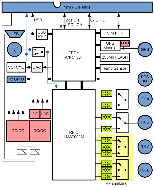
We chose the Mini PCIe form factor for XTRX because it’s the best option for a high-speed, low-latency bus that is both physically compact and widely used. In other words, using Mini PCIe results in a device that is both high-performance and easily embeddable.
While it’s true that many laptops are moving away from Mini PCIe slots and toward M.2 slots, Mini PCIe is still the most popular PCIe form factor among standards-based, professional single-board computers (SBCs) and embedded systems. We will likely release an M.2 version of XTRX after the Mini PCIe version has been delivered.
We also considered USB 3 and Thunderbolt 3, but the former is high-latency and the latter is not yet very popular. However, should you want to use USB 3 or Thunderbolt 3, there are adapter boards for both.
While Mini PCIe is a great form factor, you might need something else. That’s why we developed the USB 3 Adapter with Aluminum Enclosure and the PCIe x2 + Front End Adapter. We’re also offering Antennas + Cables known to work with XTRX. All of these are available separately, or together in the XTRX Deluxe Bundle. In addition, we’re offering a special XTRX PCIe Octopack loaded with eight removable XTRX boards.
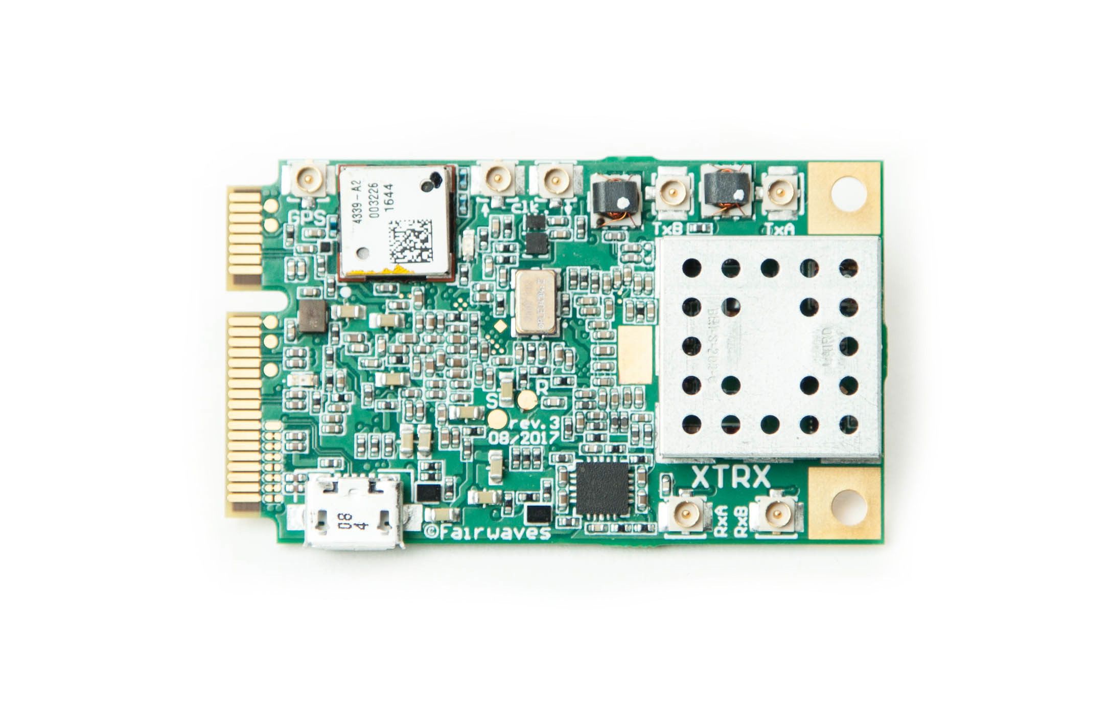
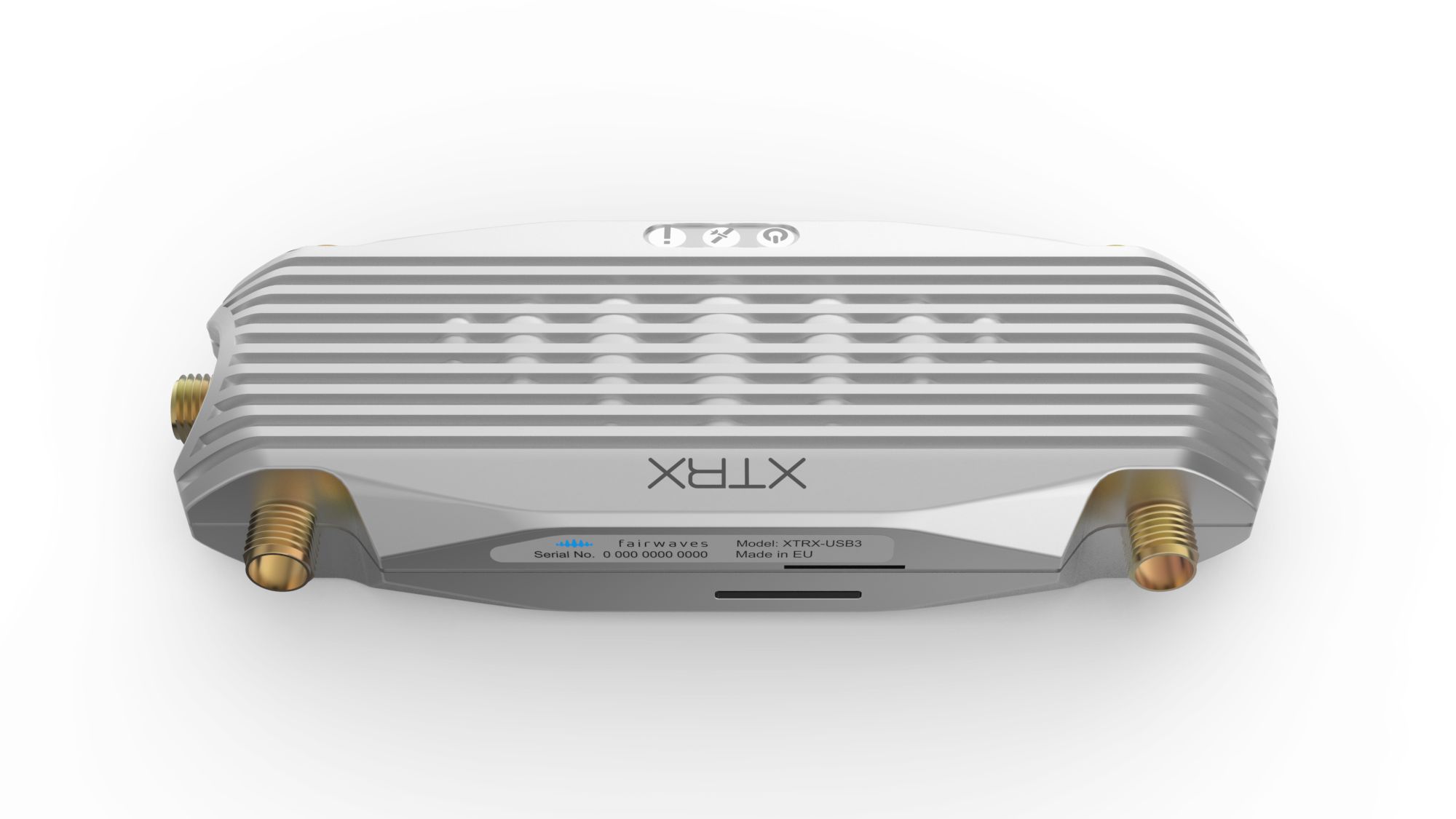
This adapter converts your XTRX from Mini PCIe to USB 3 and comes with an aluminum enclosure designed specifically for XTRX. We’re working hard to maximize the heat dissipation through the metal case so you won’t need a fan even under long, heavy loads. The adapter has three status LEDs, a micro USB 3 port, one SMA connector for the GPS antenna, four SMA connectors for the MIMO Tx/Rx antenna pairs, a micro SIM card slot, and a slot for a GPIO FPC cable. The adapter comes with a USB cable and all RF cables needed to connect an XTRX to the SMA connectors within the aluminum enclosure. The adapter does not include an XTRX, antennas, or FPC cable.
Initially, we wanted to implement USB 3 using the gigabit transceivers on the Artix 7 FPGA. This would have made the adapter really simple, but it turned out the transceivers are not capable of USB 3 out-of band (OOB) signaling. In the end, we settled on using the Broadcom USB3380 chip. You won’t get the same level of performance through USB 3 as you get in native PCIe mode, but we’ve tested running an LTE eNodeB (among other applications) through the adapter and it works well. We may realize further performance gains by taking advantage of the USB3380 chip’s internal 8051 microcontroller, which we haven’t yet utilized.
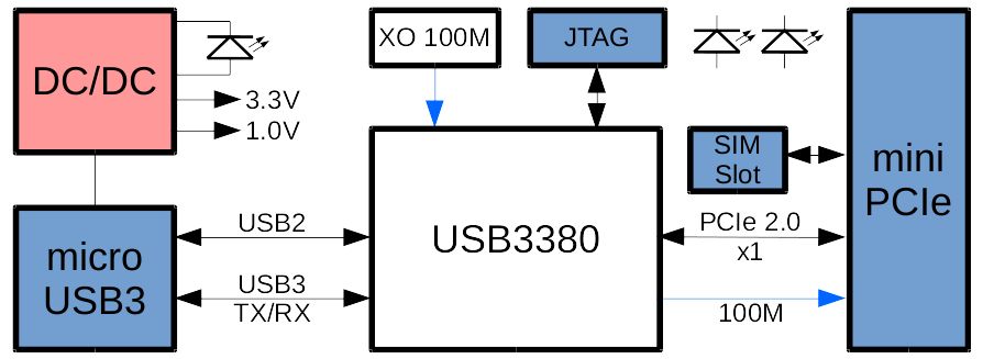
This USB 3 adapter is great for rapid application development — you can use your XTRX wherever you don’t have access to Mini PCIe, such as your laptop, you can plug and unplug on the go, reflash the FPGA image without rebooting, etc. Also, the USB3380 has four GPIO pins that we’re using for JTAG emulation, so you’ll always be able to unbrick your XTRX if your FPGA experiments go awry.
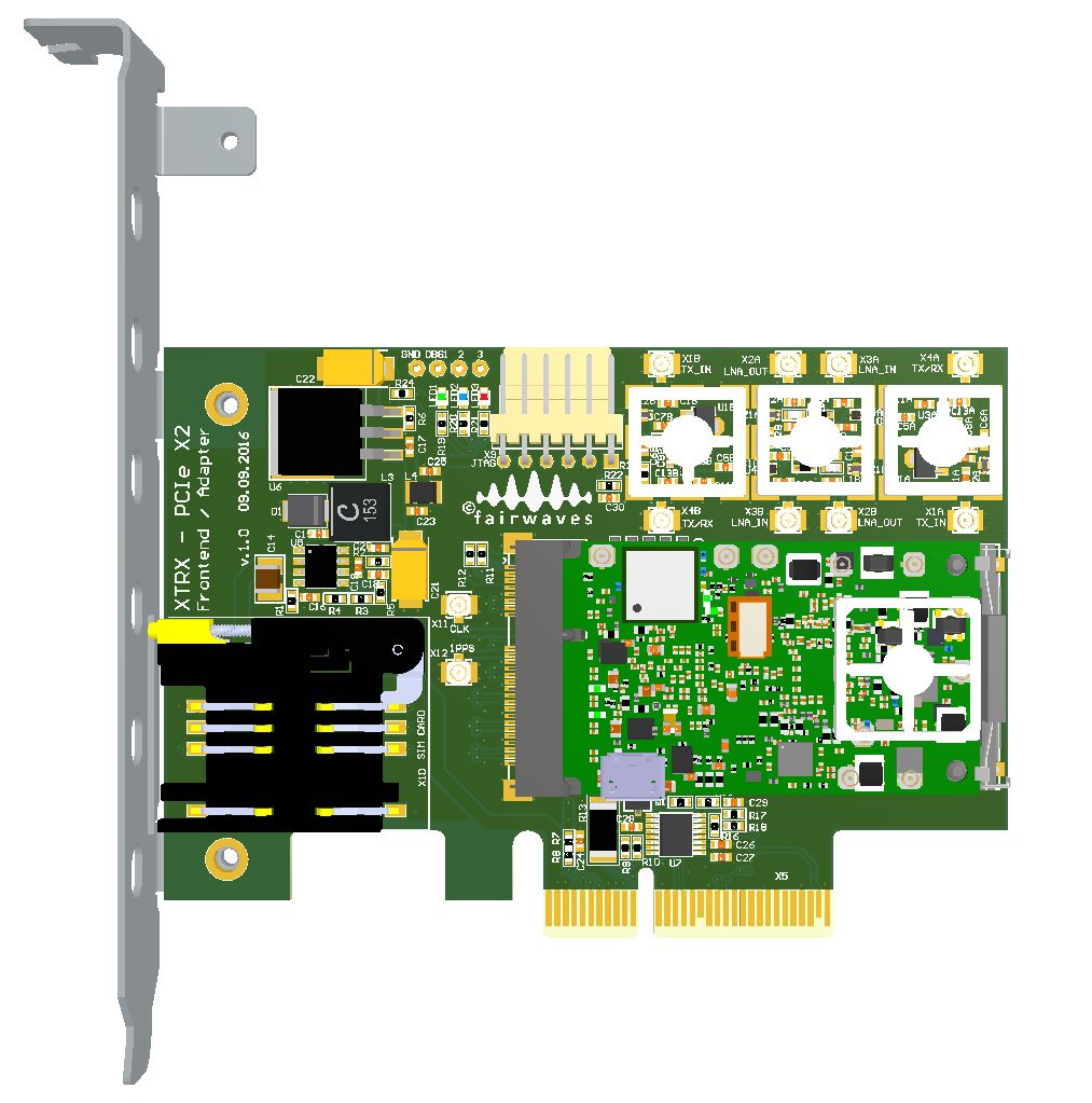
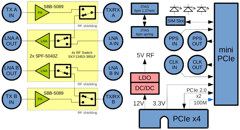
This PCIe card securely holds an XTRX board (not included) so it can be used in a standard PCIe x4 slot. It includes an RF front end with a low-noise amplifier (LNA) and power amplifier (PA) for up to 100 mW output on each channel. A time duplex division (TDD) switch is incorporated for applications like TDD LTE. You can bypass the front end by attaching cables directly to XTRX. This adapter achieves the full 10 Gbit/s raw bus bandwidth and can be plugged into x4/x8/x16 PCIe slots, though it won’t fit into an x1 slot unless the slot has an open end. A six-pin JTAG connector on the edge is compatible with a JTAG-HS2 cable, so you can easily program and debug the FPGA. The board also has a micro SIM card slot.
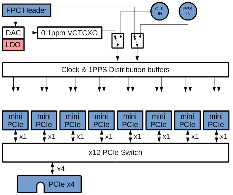
If you need a massive MIMO deployment or have a large swath of spectrum you need to monitor, you’ll want one of these limited availability Octopacks. This single PCIe card comes loaded with eight removable XTRX boards, metal installation brackets, cables for all of the GPS and MIMO Tx/Rx ports, and a special board for synchronizing all eight XTRX boards.
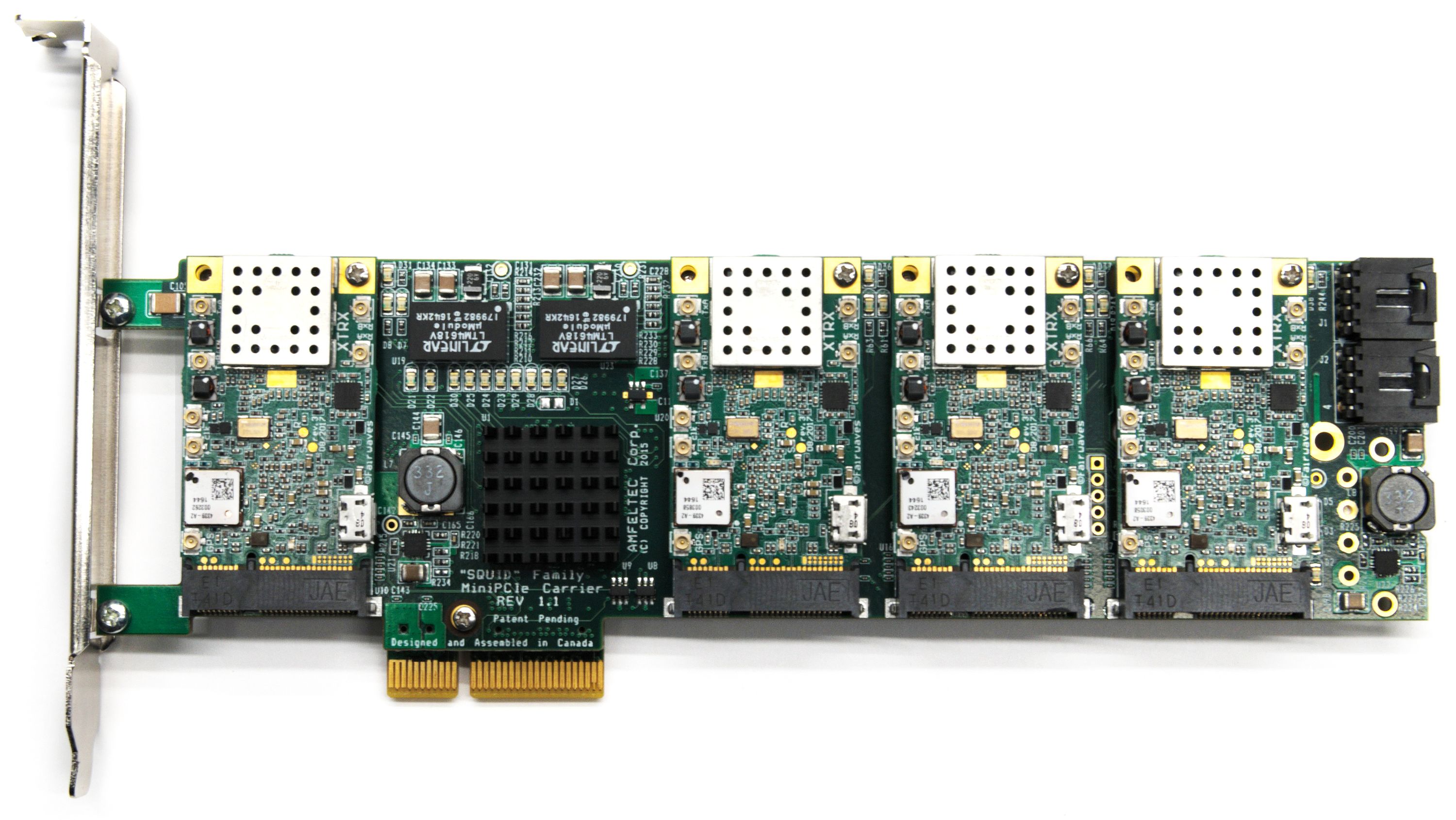
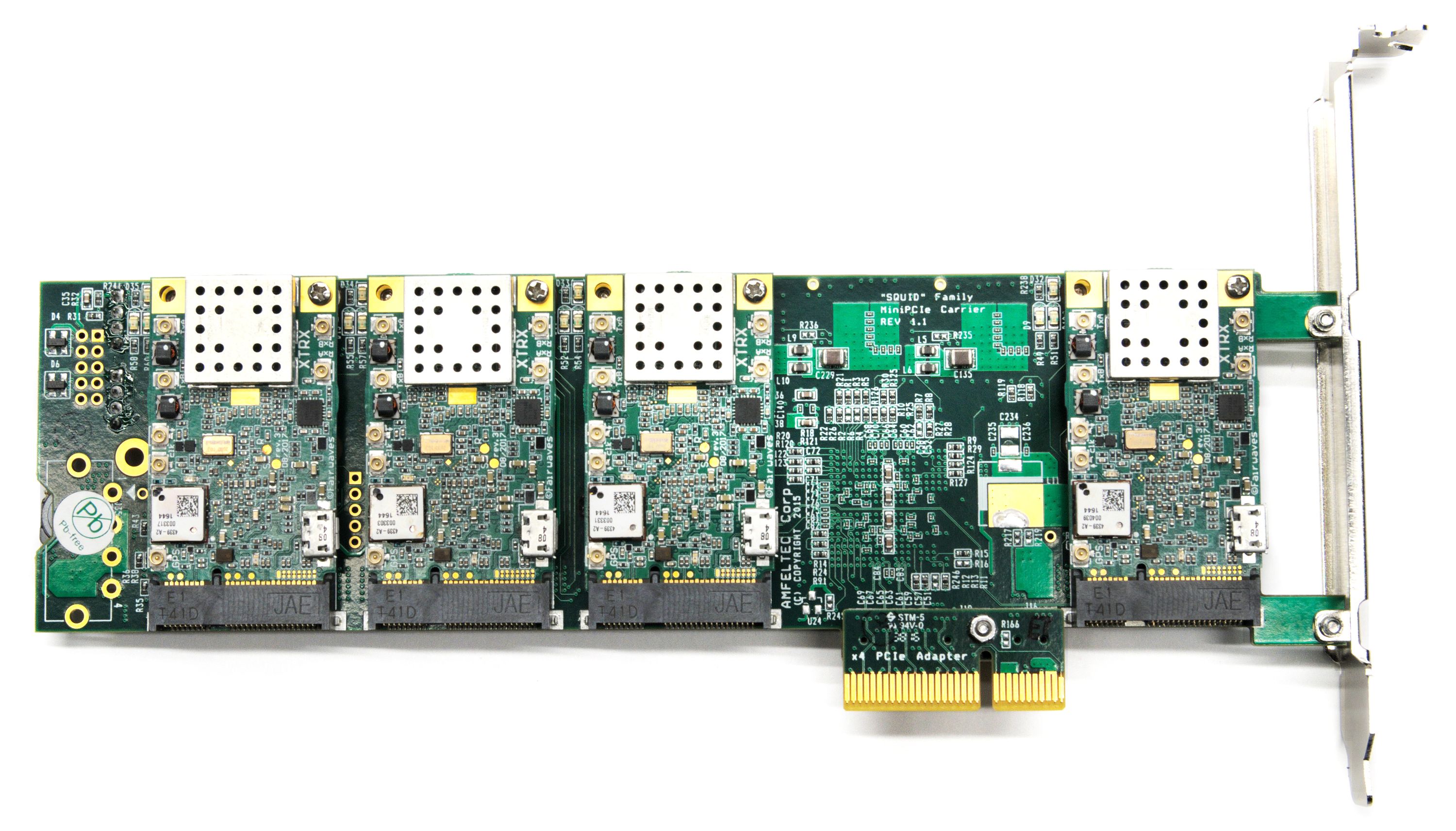
The Octopack is based on a switch that routes between a single x4 PCIe 2.0 card and eight x1 PCIe 2.0 cards. This means you can’t simultaneously utilize the full bandwidth of all eight XTRX boards, but it’s still capable of running LTE-A and other applications. All eight XTRX boards on an Octopack can be synchronized using the included sync board, which has a more stable clock generator and connects via the included FPC cable to the first XTRX. Using external clock synchronization ports (CLK_IN/PPS_IN), it’s possible to synchronize multiple Octopacks, thus creating 32 x 32, 64 x 64, or even larger MIMO systems.
The XTRX hardware itself is proprietary, though the hardware accessories we designed for it (e.g., the USB 3 and PCIe adapters) are open hardware.
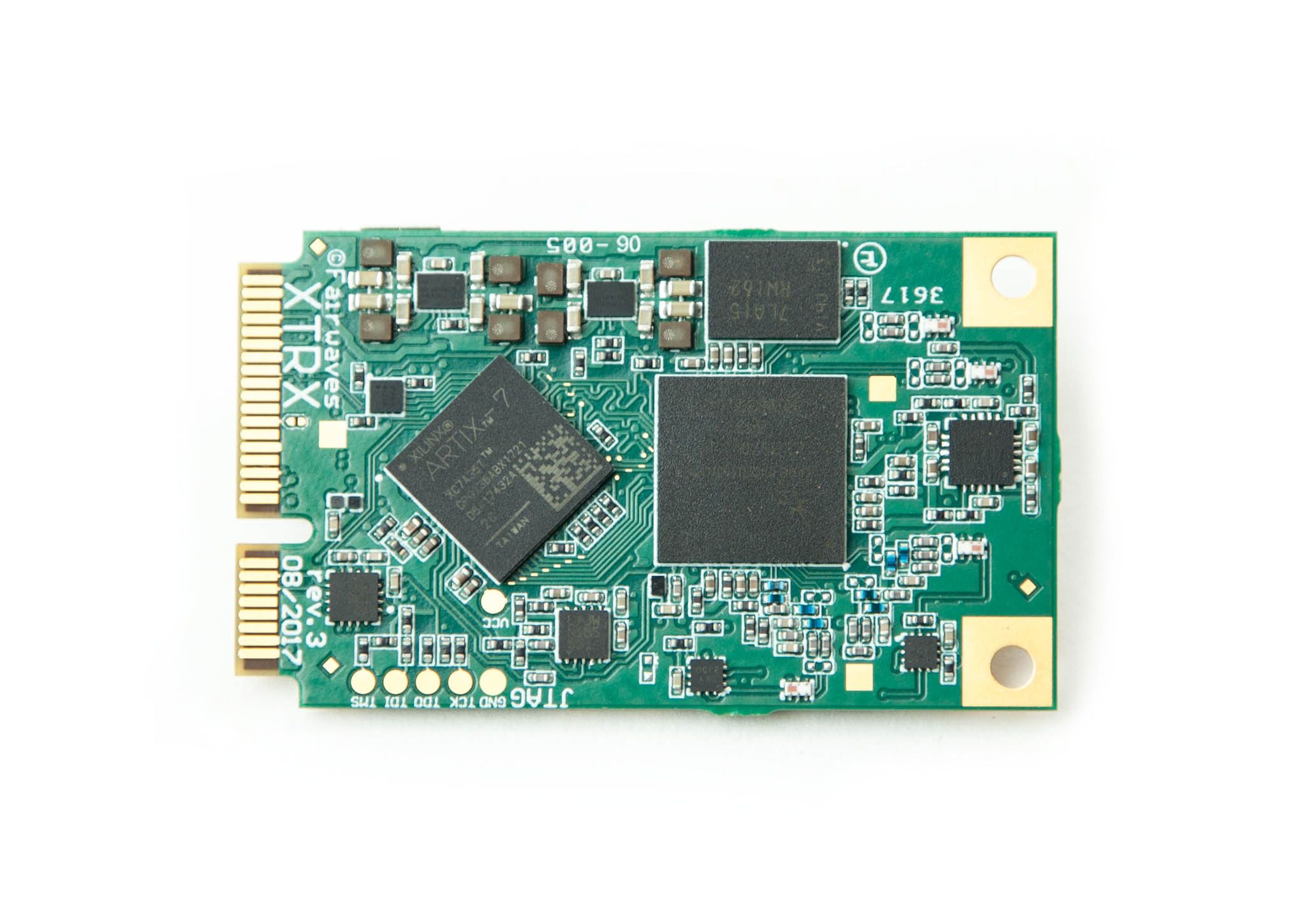
XTRX’s main FPGA code is open source and without a viral license, so not only can you modify the code, but you can also develop your own proprietary FPGA blocks. The FPGA is approximately 30% utilized. We will share a detailed utilization report in a future update. You can upload your own firmware with our USB 3 adapter board or with a JTAG cable and our PCIe adapter board. If you are good at soldering, you can even solder JTAG directly to the XTRX board — that’s how we programmed our first samples.
The host-side software and drivers are open source.
We developed our low-level API to maximize performance (i.e., we’re using a zero-copy interface). We provide a SoapySDR interface to our low-level library, so you can quickly start developing if you’re already familiar with SoapySDR. For example, using SoapySDR plugins, you can easily get UHD support. Of course, there’s always the option to interface directly to the low-level API if you don’t want to use SoapySDR or need to eek out the most bandwidth and lowest latency.
The USB 3 adapter relies on a libusb wrapper, so it will work on almost every platform libusb works on. In contrast, PCIe communication requires a kernel-level driver for direct memory access (DMA) and interrupt handling. Our host library talks to a device provided by the kernel driver. Currently, we have an implementation for Linux only. A Windows driver is in early stages of development and will be released later. We don’t plan to develop PCIe drivers for other platforms right away. Our Linux kernel driver exposes TTY devices for GPS, UART, and SIM card UART, so you can use existing software, like gpsd and xgps. The adapter also provides a kernel pulse per second (LinuxPPS) interface for handling the lowest levels of jitter in NTP-like applications.
Developing a cutting-edge product requires more than just snapping together a few ready-to-use pieces. Over the last year and a half, we’ve been through three major revisions and many minor revisions of XTRX to find the optimal ratio of price, performance, and power consumption. In order to deliver the best product possible at an incredible price, we took deep dives into many thorny issues. For example, we wrote our own PCIe DMA implementation so as to maximize bus throughput while staying within the constraints of the smallest Artix 7 FPGA.
We did this work so you wouldn’t have to. With XTRX, you can incorporate an SDR into your own designs without first becoming an expert in the rarefied art of SDR design.
At Fairwaves, we’re familiar with the problem of not being able to buy an off-the-shelf SDR. Way back in 2008, we had an idea to build an SDR-based GSM base station that could be deployed in real networks. We got a USRP1 and tried to run OpenBTS, only to struggle for days before realizing cellular standards require 0.05 to 0.1 ppm clock accuracy but the USRP1 has only 20 ppm clock accuracy. We needed a better clock, so we created ClockTamer, an open source, highly accurate, programmable clock source.
Soon after, we found the USB connection used by USRP1 was neither reliable nor easily embedded in a compact system. So, we created UmTRX, an industrial-grade SDR that became the basis of our UmSITE product, a rugged, network-in-a-box GSM base station that has been deployed around the world and has withstood everything from Saharan summers to Siberian winters.
In 2016, we started looking into 4G (a.k.a. LTE) and 5G wireless systems and realized we needed something better. Today, we’re launching XTRX to eliminate size, performance, and cost barriers to making the next generation of wireless solutions.
We are using the same manufacturing and supply chain partners for XTRX that we’ve been using for other projects over the past several years. We will release the revision 4 manufacturing files to our partners at the end of this campaign. Components procurement and PCB fabrication will take place through March 2018, followed by PCB assembly in April, testing and packaging in May, and shipping at the end of May and into June.
We will be shipping revision 4 of XTRX to backers of this campaign. The version will have only minor changes to the current revision 3, which has undergone extensive development and testing. We believe there is a very low risk that the design itself is faulty.
The biggest risk is in the supply chain, such as delays introduced by parts shortages. Though such issues can’t always be avoided, we’ve been manufacturing SDRs since 2013 and we know how to reduce the likelihood of issues and to mitigate their effects. Regardless, we commit to communicating openly and honestly about manufacturing progress. Be sure to subscribe to the project updates to get the latest news.
Produced by Fairwaves in Boston, USA and London, UK.
Sold and shipped by Crowd Supply.

Like what we do and want to see more advances in software-defined radio? Pitch in to the tip jar!

Get an XTRX CS revision 4 board. Does not include any cables, antennas, or adapter boards.

Get an XTRX CS revision 4 board as well as an Antennas + Cables set, a PCIe x2 + Front End Adapter, and a USB 3 Adapter with Aluminum Enclosure (see below for details). Also comes with four extra U.FL-to-U.FL cables and four extra U.FL-to-SMA-male cables.

A full complement of cables and antennas for your XTRX, including four RF antennas (95 mm, 2 dBi, SMA male, GSM/3G/LTE 880 - 960 MHz, 1710 - 1990 MHz), one GPS antenna, and five cables.

From the Crowd Supply Basics project.
Abracon External Antennas exhibit low return loss characteristics, high gain, and Low Voltage Standing Ratio (VSWR). These external antennas are linearly polarized and come in a low profile package.

From the Crowd Supply Basics project.
A Hirose U.FL to SMA (jack) bulkhead straight connector with a 1.32 mm diameter cable. Less than -2 dB cable insertion loss up to 6 GHz. Both connectors are gold-plated brass and the cable conductor is silver-coated copper.

From the Crowd Supply Basics project.
A low-noise active GPS antenna suited for the GPS L1 band. Accepts 3-5V DC and outputs RF via an SMA(m) connector. Optional adhesive mounting.

This adapter converts your XTRX from Mini PCIe to USB 3 and comes with an aluminum enclosure designed specifically for XTRX. The adapter has three status LEDs, a micro USB 3 port, one SMA connector for the GPS antenna, four SMA connectors for the MIMO Tx/Rx antenna pairs, a micro SIM card slot, and a slot for a GPIO FPC cable. Comes with a USB cable and all RF cables for internally connecting an XTRX to the SMA connectors. Does not include an XTRX, antennas, or FPC cable.

This PCIe card securely holds an XTRX board (not included) so it can be used in a standard PCIe x4 slot. It includes an RF front end with a LNA and PA for up to 100 mW output on each channel. A TDD switch is incorporated for applications like TDD LTE. You can bypass the front end by attaching cables directly to XTRX. This adapter achieves the full 10 Gbit/s raw bus bandwidth and can be plugged into x4/x8/x16 PCIe slots. A six-pin JTAG connector makes it easy to program and debug the FPGA. A micro SIM card slot is also present.

This single PCIe card comes loaded with eight (8!) removable XTRX CS boards, metal installation brackets, enough cables for all GPS and MIMO Tx/Rx ports, and a special board for synchronizing all eight XTRX CS boards.
Here's your chance to get an XTRX CS board as soon as possible. We'll send you an XTRX CS revision 3 board as soon as the campaign reaches its funding goal and we'll follow up with a production version (revision 4) as soon as they come off the assembly line.
Get an XTRX revision 4 board at a nice discount from the regular campaign price. Does not include any cables, antennas, or adapter boards.
This single PCIe card comes loaded with eight (8!) removable XTRX boards, metal installation brackets, enough cables for all GPS and MIMO Tx/Rx ports, and a special board for synchronizing all eight XTRX boards. There are only five Octopacks available at this price - if these are depleted, the next batch will be at least $2,900 each.

We are a vertically integrated vendor of cellular equipment focused on the needs of emerging markets. We are developing, manufacturing, deploying, and operating turn-key cellular network solutions including radio equipment, towers, power and backhaul all the way to a core network and SS7 interconnect. Our team has been building software-defined radios and systems based on them since 2009 and is well known for its ClockTamer, UmTRX, and UmSITE products.


Everything you need to navigate the world's largest electronics market

An open source FT2232H-based, multi-protocol, multi-voltage tool for hardware hacking
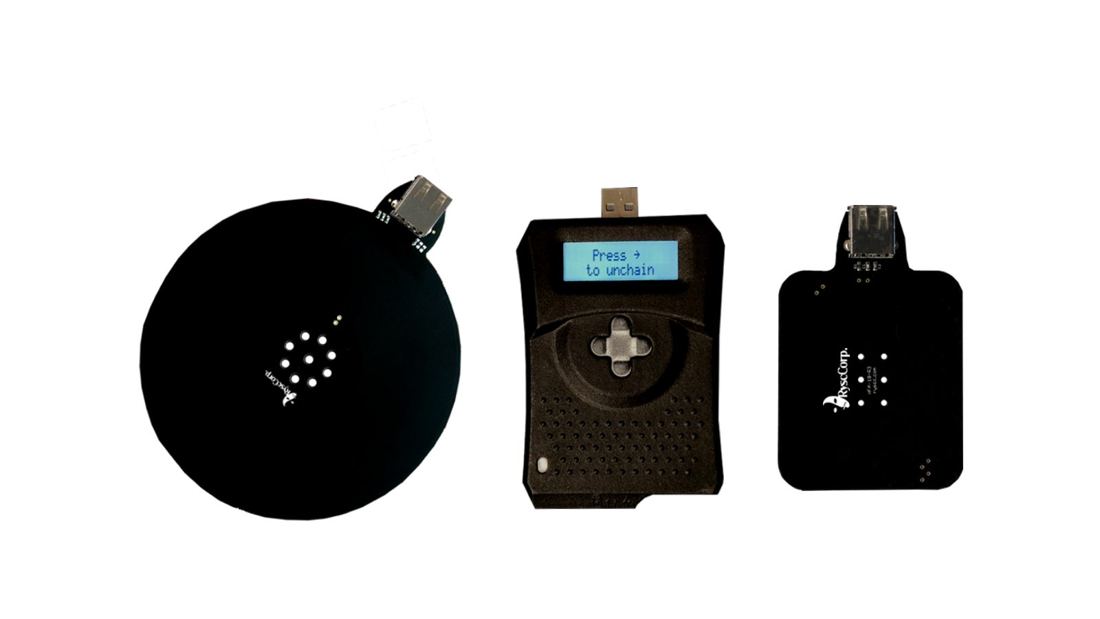
A handheld RFID & NFC test instrument optimized for untethered use in the field