Project update 3 of 5
Packaging Design Files for Manufacturing
by Jay HIn the spirit of open source, we don’t just want to provide the underlying design files, we also want to make it as easy as possible for you to incorporate NRFICE technology into your own development projects. Once your design is complete, from an engineering perspective, you’ll need to package all the right files into a single zip archive (a "quote package") and send it to your contract manufacturer (CM) for a quote and a time line estimate.
Sometimes we prefer to order bare PCBs, separately order the needed parts, and do the soldering ourselves. This can save time in a phase where the board will be used to continue research and development of the design. In the case of NRFICE, we went with a complete "turnkey" build, which is where the CM sources all the components, fabricates the PCBs, assembles the finished boards, and ships the fully assembled product to us.
For those of you who might not be familiar with this process, we will run through the elements of a typical turnkey quote package below:
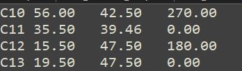
Assembly File
This is the part-location data used to program a pick-and-place machine. It is simply a text file that contains the designator, x-position, y-position, and rotation angle of each component to be placed.
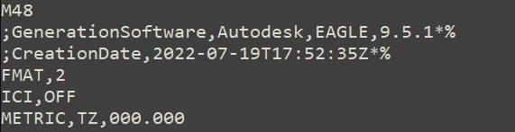
Drill Files
The drill file, as its name suggests, includes data for through-hole drilling and vias. We generate ours using Eagle, and they look like this:
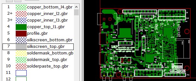
Gerber Files
Gerber files represent the exact locations and paths where copper, solder mask, and silk screen (also known as "PCB legend") should be placed. The number of files in this folder will depend on various things, including the number of layers in your PCB and whether you need solder mask or silk screen on the top, on the bottom, or both. We use Pentalogix ViewMate to work with our Gerber files.
Bill of Materials (BoM)
Of utmost importance is the spreadsheet containing the bill of materials. In our experience, the BoM is where errors are most likely to occur. Gerber files, for example, are generated by CAD software, which performs its own electrical rules check, so it’s rare for Gerbers to have missing copper, a shorted signal, etc. But with the BOM, we manually identify components to maximize quality and reduce cost, we sometimes have to deal with multiple component substitutions, and we often add other notes to the manufacturer, so there is a lot more opportunity for human error.

Note that in addition to specifying the manufacturer, part number, designators, and other part-specific information, we also need to clarify whether a component is to be mounted on the top or bottom of the board and what mounting technology—such as through hole or _surface mount_—should be used. The CM will need all of this information in order to calculate the cost of production. Finally, the "points" field is the number of pins on each part, which is used to calculate the cost of testing the PCB for continuity.
Thanks to Our NRFICE Supporters
While the NRFICE campaign is now well past its funding goal, new backers are always welcome!