Project update 4 of 5
A Look at Our Firmware & How to Modify It
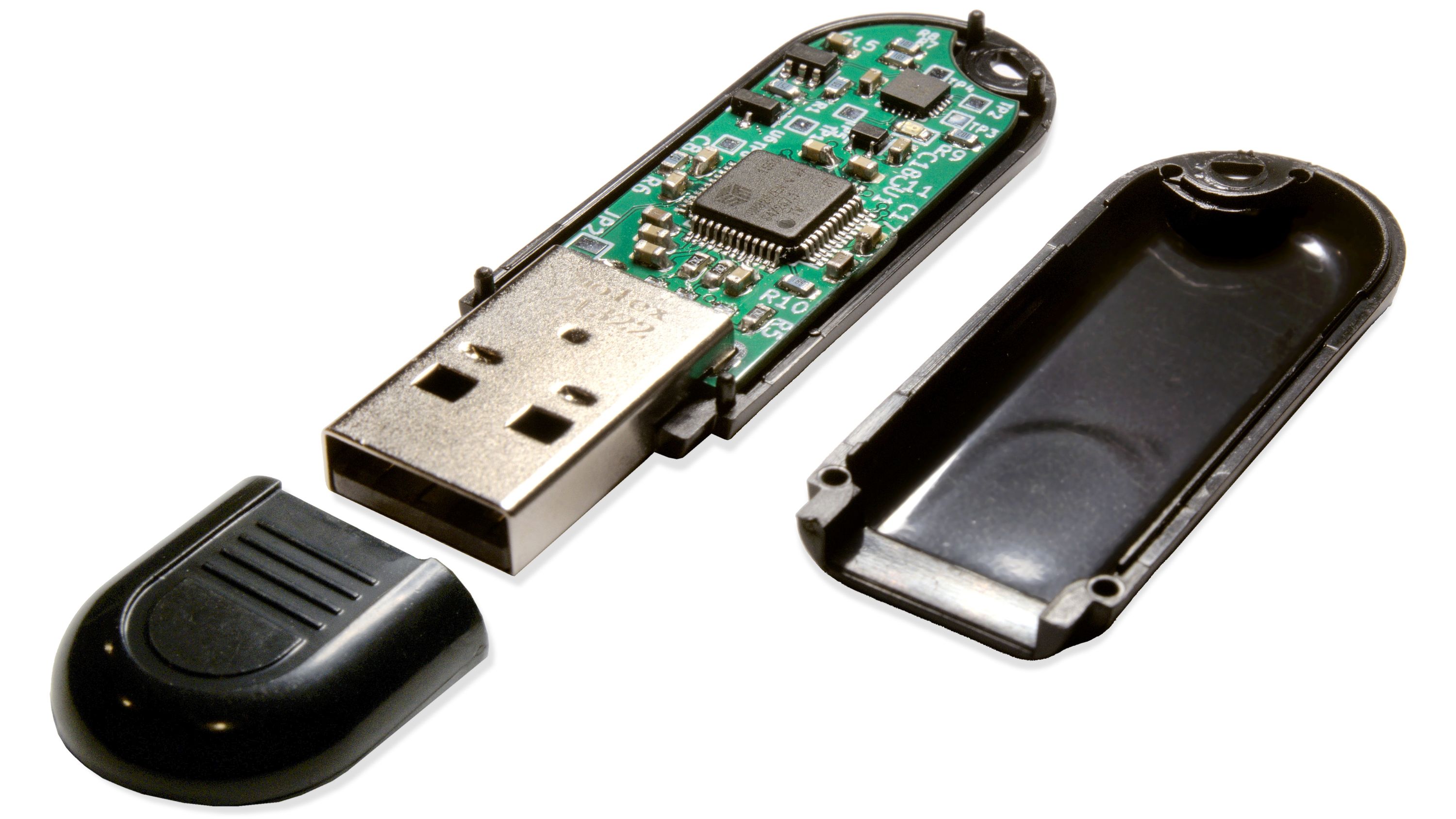
by Ryan WalkerOvrdrive USB is an open-hardware USB flash drive with an inconspicuous enclosure and a hidden security feature tucked away inside it. If you plug the device in normally, it will appear blank, but if you quickly plug it in three times in a row, you can read and write data. We built Ovrdrive for journalists working in hostile environments, security researchers, and anyone interested in open hardware.
Our campaign is nearly over, and I couldn’t be happier about bringing this product to life. Thank you for your support, and please keep in mind that our price will increase slightly after the end of the campaign on Thursday.
In this update, I will go over the device firmware and programming.
Programming the Ovrdrive Microcontroller
I chose a very simple microcontroller that has been around for a while, the ATtiny24. It’s a single RISC core with just 2 KB of flash and 128 KB of RAM. I chose it because it’s affordable, abundant, and operated at 5 V, so I could avoid using a voltage regulator, as space was limited on the board.
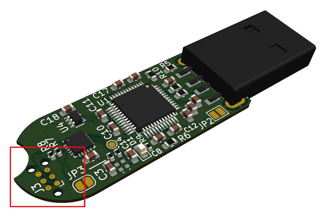
Ovrdrives will all come pre-programmed, of course, but if you want to modify the code, you can. The chip is programmed using an AVR ISP (or Arduino acting as a programmer) and connected to the programming port of the board using a TC2030 cable.
I realize the TC2030 is an expensive cable that not everyone can access, but I’ll explain why I used it and some workarounds. Previously, I used a 0.1 mm pitch header, but, without soldering down the headers, I couldn’t get it to make reliable contact for programming. And once soldered down, the board will no longer fit in the enclosure, leading me to the 2030. As a workaround, the TC2030 land has the same pitch as a 0.1 mm pitch cable, so, for a quick program, I think you might be able to hold a header to the pads. I will test this soon and update everyone.
I’ll add the source code below, but you can also find it here.
Main Source File
#include <avr/io.h>
#include <util/delay.h>
#include <stdbool.h>
#include "ovrdrive.h"

void enable_flash(void) {
    PORT_IN1 |= (1 << PIN_IN1);
    PORT_IN2 &= ~(1 << PIN_IN2);
}

void destroy_flash(void) {
    _delay_ms(3000);
    PORT_LED |= (1 << PIN_LED);
    _delay_ms(5000);
    PORT_LED &= ~(1 << PIN_LED);

    // If the pin is high, someone
    // cut the trace, enabling the
    // destructing circuit.
    if((PORT_I_FSD & (1 << PIN_FSD)) && !SAFE) {
        while(true) {
            PORT_IN1 &= ~(1 << PIN_IN1);
            PORT_IN2 |= (1 << PIN_IN2);
            _delay_ms(10);
            PORT_IN1 |= (1 << PIN_IN1);
            PORT_IN2 &= ~(1 << PIN_IN2);
            _delay_ms(10);
        }
    }
}

void inhibit_flash(void) {
    PORT_INHIBIT |= (1 << PIN_INHIBIT);
}

void set_chg(char pin) {
    DDR_CHG  |=  (1 << pin);
    PORT_CHG |= (1 << pin);
}

bool check_chg(char pin) {
    if(PORT_I_CHG & (1 << pin))
        return true;
    return false;
}

int main(void) {
    DDR_IN1  |= (1 << PIN_IN1);
    DDR_IN2  |= (1 << PIN_IN2);

    DDR_FSD  &= ~(1 << PIN_FSD);
    PORT_FSD |= (1 << PIN_FSD); // Enable pullup

    DDR_INHIBIT  |=  (1 << PIN_INHIBIT);
    PORT_INHIBIT &= ~(1 << PIN_INHIBIT);

    DDR_LED      |=  (1 << PIN_LED);
    PORT_LED     &=  ~(1 << PIN_LED);

    DDR_CHG  &=  ~(1 << PIN_CHG1);
    DDR_CHG  &=  ~(1 << PIN_CHG2);

    enable_flash();

    bool enable = false;
    if(check_chg(PIN_CHG1)) {
        if(check_chg(PIN_CHG2)) {
            enable = true;
            PORT_LED |= (1 << PIN_LED);
        }
        else {
            set_chg(PIN_CHG2);
        }
    }
    else {
        set_chg(PIN_CHG1);
    }


    if(enable)
        enable_flash();
    else {
        inhibit_flash();
        destroy_flash();
    }

    while(true) {
        // Twiddle
    }
}
The above isn’t the final firmware; I still have to make a few tweaks and do final testing, but it’s very close. It essentially just enables the pin directions, performs the check to see if the caps are charged up (for multiple insertion detection), and either enables or disables the flash, with the optional destruction depending on how you’ve configured the device. (To enable the heating circuit, you must cut a trace on the PCB.)
Header
/* Production Variables */
#define SAFE false // Don't ARM FSD cct. ?

/* IN1 / IN2 DRV8837C */
#define PIN_IN1 PA0
#define DDR_IN1 DDRA
#define PORT_IN1 PORTA
#define PIN_IN2 PA1
#define DDR_IN2 DDRA
#define PORT_IN2 PORTA

/* Flash Inhibit Signal */
#define PIN_INHIBIT PA2
#define DDR_INHIBIT DDRA
#define PORT_INHIBIT PORTA

/* LED */
#define PIN_LED   PA7
#define DDR_LED   DDRA
#define PORT_LED  PORTA

/* Charge Pins*/
#define PIN_CHG1   PB0
#define PIN_CHG2   PB1
#define DDR_CHG    DDRB
#define PORT_CHG   PORTB
#define PORT_I_CHG PINB

/* Full Self Destruct Select */
#define PIN_FSD     PA3
#define DDR_FSD     DDRB
#define PORT_FSD  	PORTA
#define PORT_I_FSD  PINA
The header simply defines some pins.
Makefile
# Generic AVR Makefile
# Fuse Programming Take from: http://www.engbedded.com/fusecalc/

MCU_TARGET     = attiny24

# Target file name
TARGET = ovrdrive

# List of C source files and object files
SRC =	$(TARGET).c

# Executable names
COMPILER = avr-gcc
COPY = avr-objcopy
DFU = avrisp2

# Generated user string
USER = $(shell whoami)

# Misc arguments
FRQ = 8000000
DEFS = -Wp,-DF_CPU=$(FRQ)UL
LIBS = -lm
OPT = s #s = size, 0 = none, 3 = maximum
STD = gnu99

build: version
    @echo =====Compiling=====
    $(COMPILER) -mmcu=$(MCU_TARGET) $(DEFS) -O$(OPT) $(LIBS) -std=$(STD) $(SRC) -o $(TARGET).elf
    @echo =====Making .hex File=====
    $(COPY) -O ihex -R .eeprom -R .fuse -R .lock -R .signature $(TARGET).elf $(TARGET).hex
    @echo =====Build Done=====

version:
    @echo =====Version=====
    @$(COMPILER) --version
    @echo =================

flash: build
    @echo =====Programming Board=====
    avrdude -p $(MCU_TARGET) -c $(DFU) -e -U flash:w:$(TARGET).elf
    @echo =====Programming Done=====

fuse:
    -avrdude -p $(MCU_TARGET) -c $(DFU) -U lfuse:w:0xe2:m -U hfuse:w:0xdf:m -U efuse:w:0xff:m

clean:
    @echo =====Cleaning=====
    rm $(TARGET).elf $(TARGET).hex

rebuild: clean build
all: build flash fuse
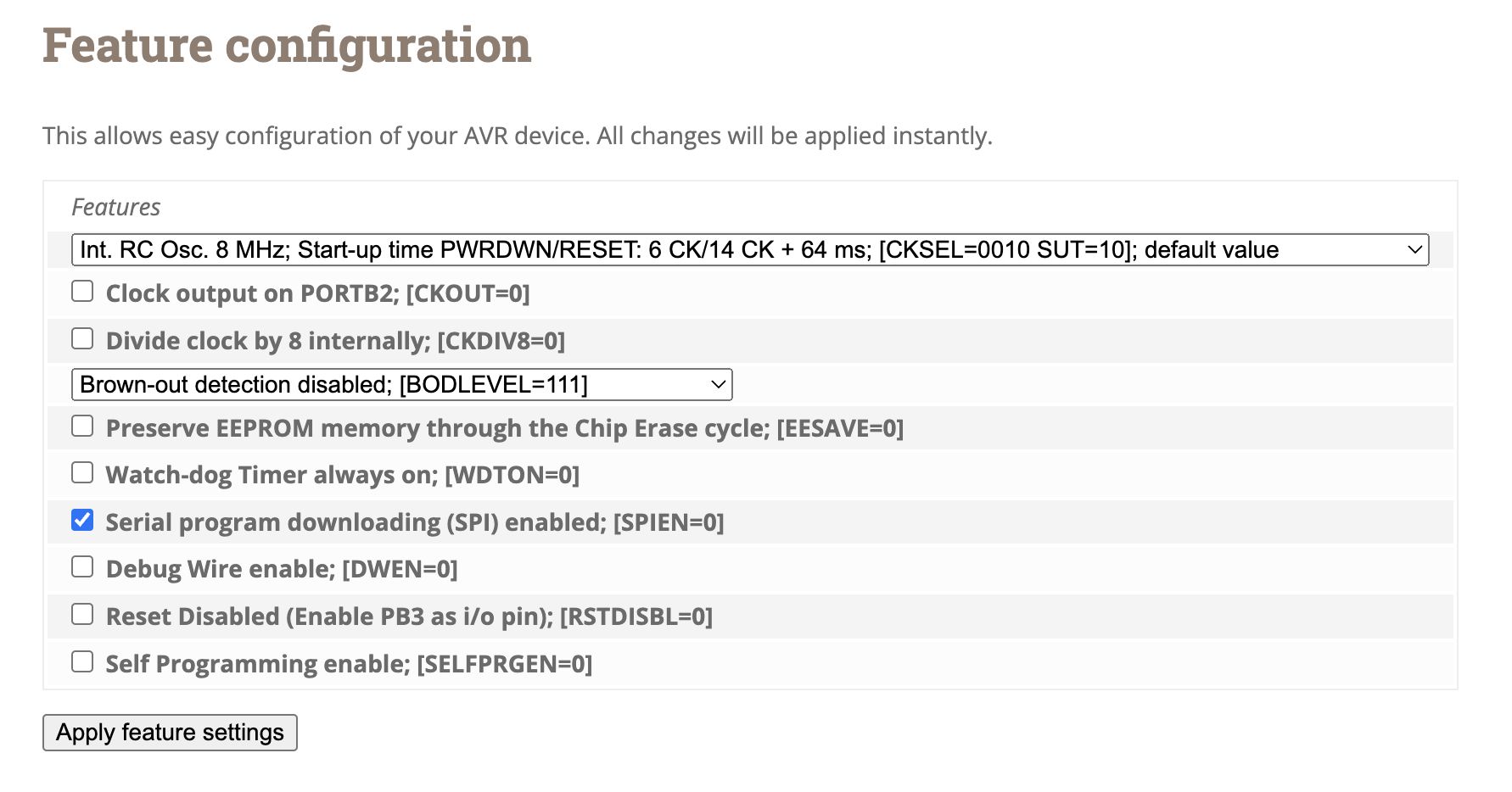
The makefile defines the device, compiles everything with gcc, and has the option to flash the MCU using avrdude. There is also a fuse flashing option, which sets various chip parameters. These hex values are determined by this nifty site (or manually). See the current fuse settings below.
Thanks for tuning in!
-Walker