1btn is not just an open source product, it is also an open hardware design. This means proud owners of 1btn have access to its firmware, its hardware design files, and, of course, the actual hardware.
While you already have an overview of technical specifications for 1btn, today we’re going to go through a detailed tear down of everything packed inside 1btn’s case.
If you have an unsealed 1btn, you can easily pry open the case a finger-nail, small blade, or flat-head screwdriver. However, if you’ve got a sealed version, be extremely careful while doing this as excessive force could damage the case top or bottom.
A high level view
1btn is comprised of four main parts:
- top case
- bottom case
- PCB assembly
- LiPo battery
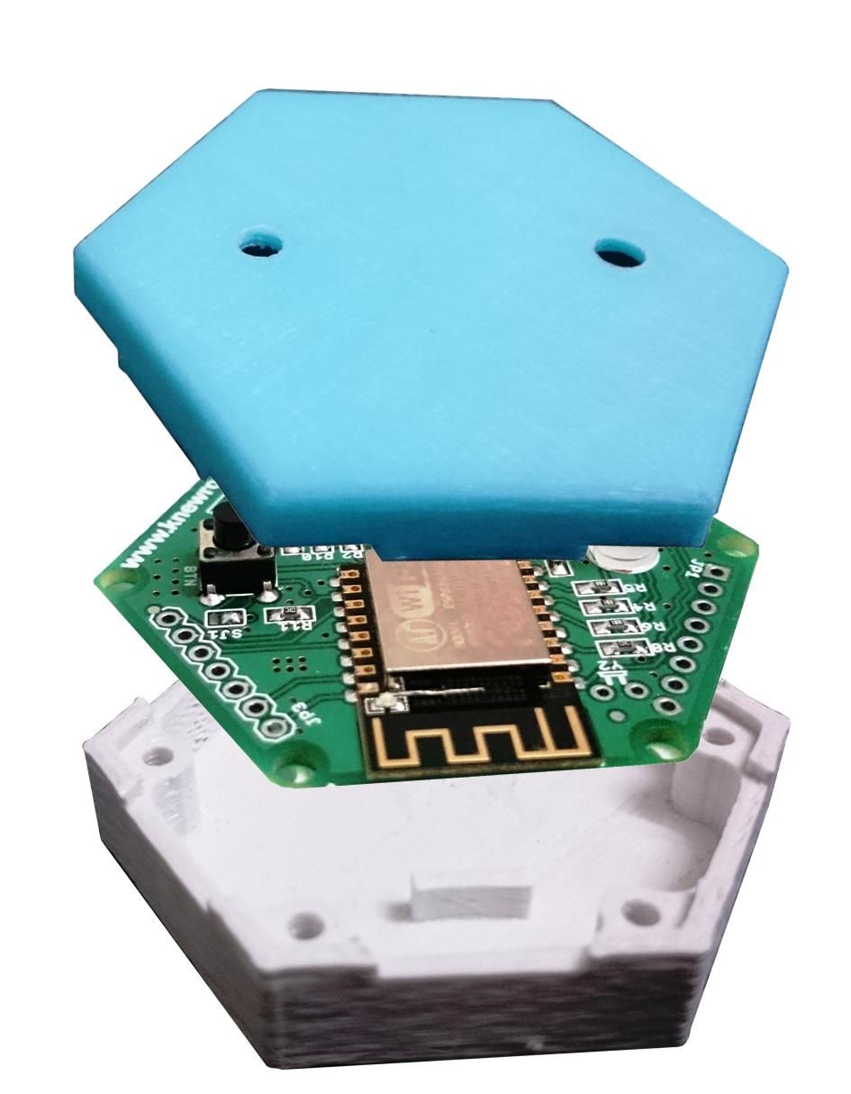
Exploded view in figure 1 shows these four parts. Did you notice the two small ribs in the middle of bottom case? They are meant for fitting the battery snugly between them. Unfortunately, LiPo batteries do not come in uniform size despite being same capacity and therefore there are two designs of bottom casing. One is with these ribs and one is without – to accommodate slightly wider batteries.
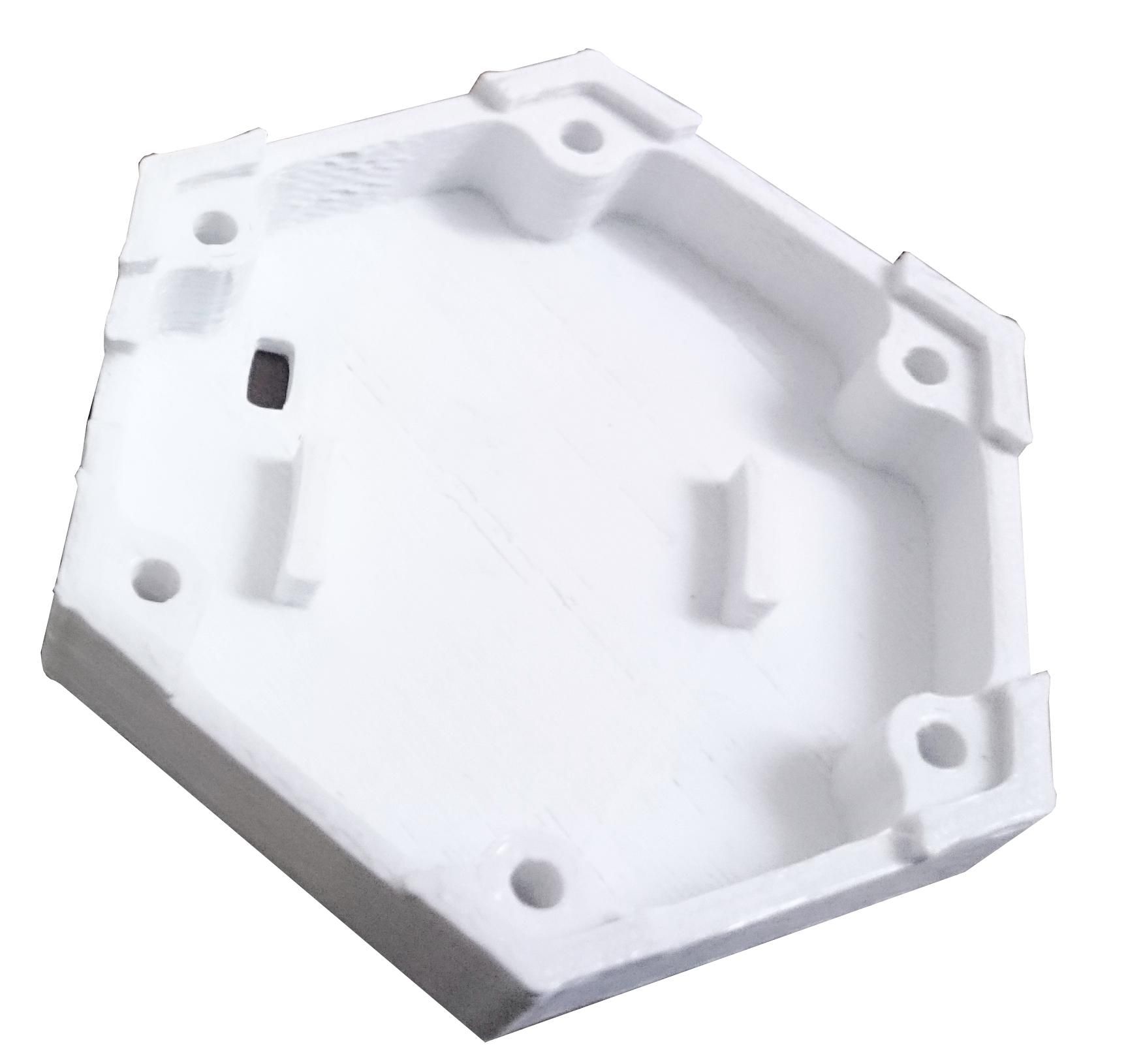
The 1btn PCB assembly rests on the six mounting holes molded into the bottom casing which maintains enough distance between the battery and PCB assembly. Interestingly, if you want to keep the internals of the 1btn accessible, you could use 3mm screws (insert from bottom side of casing) to tightly join top and bottom case with the PCB assembly sandwiched in between.
More about PCB assembly
The 1btn PCB is a double sided board with components placed on both sides, though mainly on top. though. Figure 3 shows that there is 3.3V regulator IC placed just under ESP module which is not visible in other shots of the 1btn. That’s because the board is designed to accommodate two different voltage regulators. This gives us the manufacturing flexibility to use whichever part is available and populate the board accordingly.
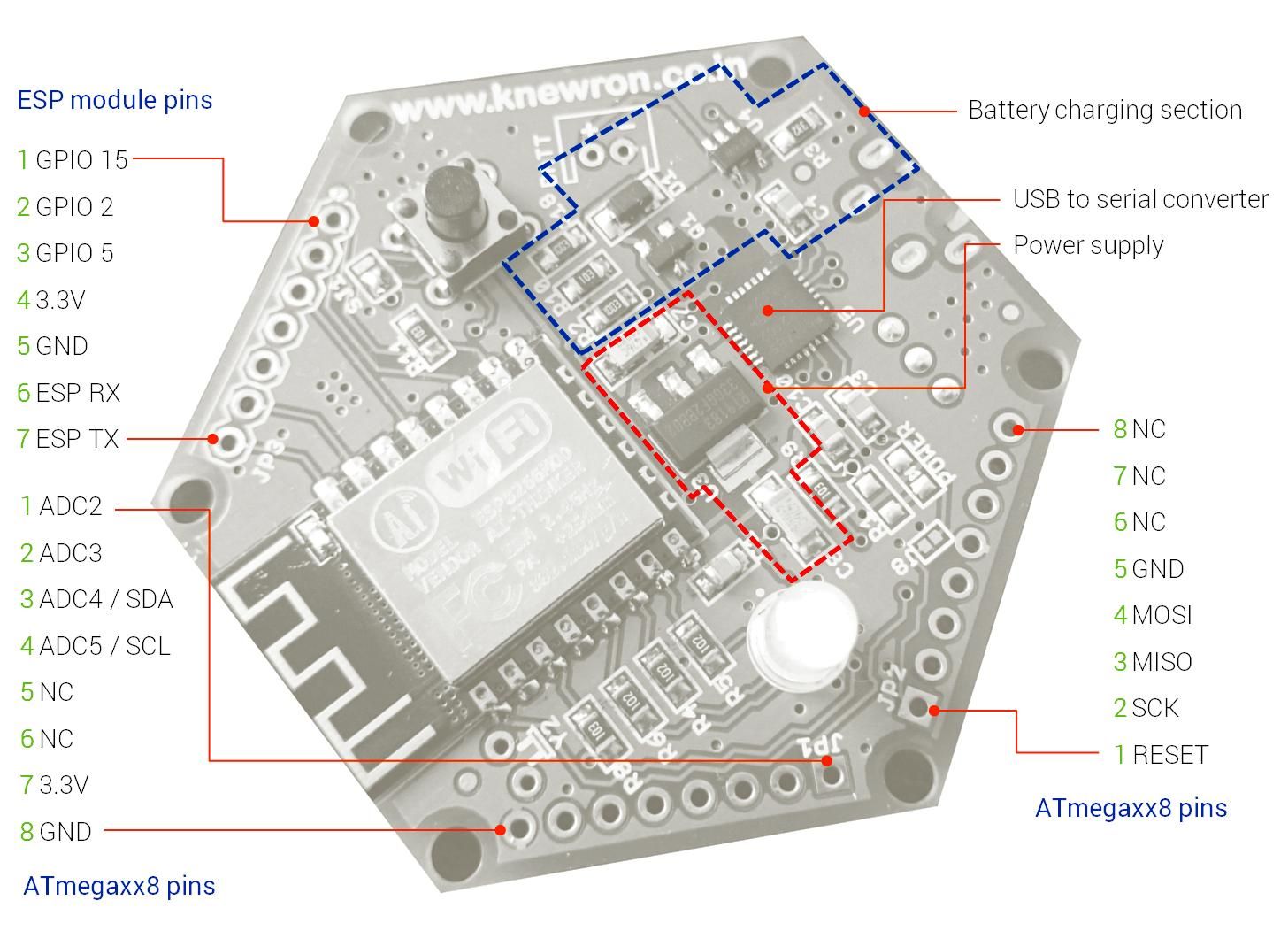
You can also see that there are three expansion ports on the board —JP1, JP2 and JP3—which essentially provide extensions for ESP, ISP and analog pins of an ATmegaxx8P controller, space for which is included on the bottom of the PCB. Adding an ATmega controller can considerably extend the capabilities of 1btn by allowing you to add sensors and multi-press functionality. Figure 4 shows the bottom side of the PCBA where you will see four major sections:
- The USB port
- The on-off switch of 1btn
- An array of jumpers
- Footprint for adding an ATmegaxx8P controller chip. You can use any variant from ATmega328P, ATmega88/V or ATmega168/V and similar.
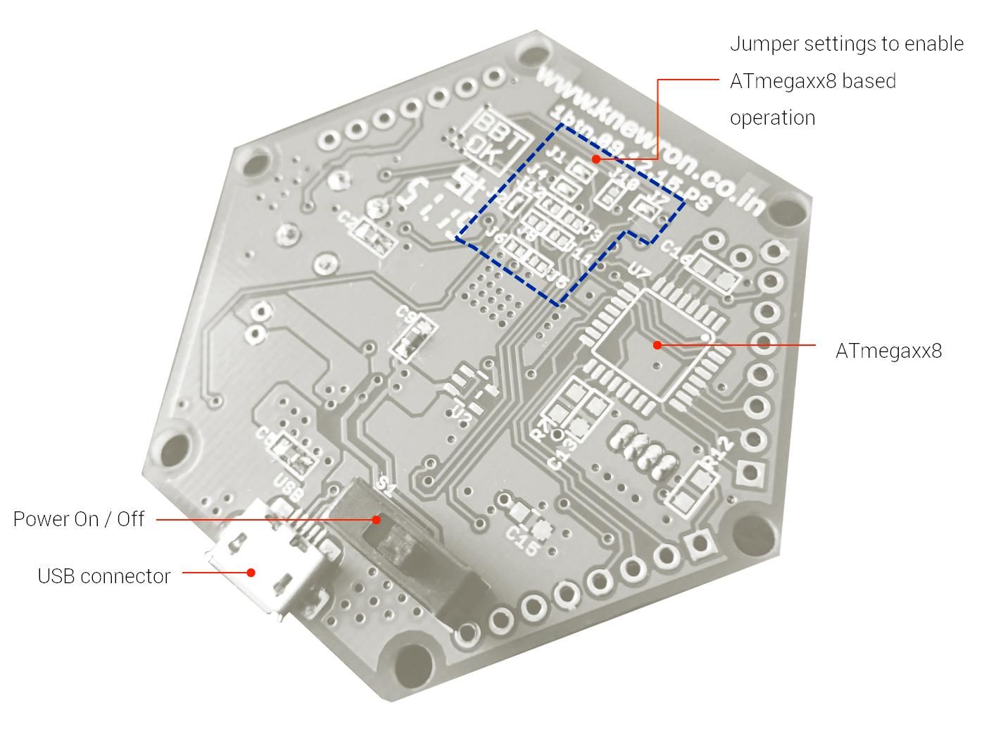
In order to enable ATmega based operation, a few jumper settings need to be changed, more information on that will be available on GitHub by later next week (see the BOM). This will give you the power of ATmega along with ESP power, a great combination! Why you would do that, you may ask? For starters, with addition of an ATmega chip, you can basically convert 1btn into a multi-press device. Plus, adding extra sensors to the power of wifi has almost unlimited potential for new applications.
Basically, if you hack 1btn this way, it can change fundamental functionality into something completely different, novel, nifty and interesting.
About the battery charger of 1btn
One of the interesting things about 1bth’s battery charging circuit of 1btn is that you don’t have to turn the button ON to charge the battery. The on-off switch is placed after the battery charger and before the regulator circuit which lets you enter charge mode while the switch is still in off position.
1btn is open source hardware
All the components are chosen in such a way that they are easily available at lower MOQ or single piece quantities, everywhere. Most of the passive components are in 0805 / 0603 packages which are easy to hand-solder. And there is absolutely nothing complicated on the board which would discourage a maker / hacker from playing around.
Designing for manufacturing as well as for inventory and part substitutions is very important when working on an open source design. We do this to ensure that if part A is not available then part B (or part C) can be used instead without hampering functional or safety aspects.
I strongly believe that when making open source hardware, it is important to keep makers in perspective and design the product accordingly. Using unnecessarily sophisticated parts and hard to work with miniature components works against the spirit of play that encourages the community to improvise, enhance, and experiment.
All the design files of 1btn are currently being developed and will be made available on github very soon.
In the end…
A few weeks ago geek.com had this to say about 1btn:
“1btn is a powerful, open source, do-it-all button for the Internet; it can already do a lot, and once there’s a community hacking away at it, the possibilities are virtually limitless.”
Happy hacking with 1btn!