Project update 4 of 7
Using EsPiFF to Build a USB Test and Measurement Device Using USBTMC
by Steffen Wittenburg, Michael SchmidHello EsPiFFers, welcome to our latest update.
Today, we look at the possibility of using the EsPiFF to build a USB test and measurement device using USBTMC. For a lab or automated test setup, engineers often connect their test and measurement equipment over USB and then remote control it with PC software like LabView, Sigrock, or Octave. These all support a standard called USBTMC. A given setup might combine oscilloscopes, multi-meters, power supplies, and all kind of specialized test and measurement equipment. Measurement gear from big brands is expensive: for example a USBTMC-to-ethernet protocol converter from Agilent costs $2k (USD). Using EsPiFF reduces these cost dramatically. It also offers the possibility of building your own standard-conforming USBTMC lab gear, such as power supplies, function generators, oscilloscopes, DAQs, and so on.
There are over 1000 different Pi HATs available, for all kinds of uses. What if we could access all of them over USB to use them with LabView, Sigrock or Octave? Today, we’ll lay the groundwork to make this possible.
What’s needed:
- An EsPiFF
- One (or more) Pi HATs, such as the wave-share [High-Precision AD HAT]https://www.waveshare.com/wiki/High-Precision_AD_HAT, or our analog/digtal HAT
- A USB-A to USB-A cable
The above HATs are just examples, any HAT that measures or sets something could be used as well. A side note: the USBTMC standard specifies a a USB-B connector for USBTMC devices, but we are using a USB-A connector on the EsPiFF. The EsPiFF’s USB-A port is a dual role port, it can be host or device. So, while this does not conform perfectly to the USBTMC standard, we can live with it.
With the hardware components in hand, we now need to program the RP2040 as a USBTMC device, in addition to operating the HAT. Luckily, the TinyUSB stack for the RP2040 supports USBTMC, so we just need to do some small modifications to our template.
For further information, take a look at this USBTMC device example code and this specific RP2040 example.
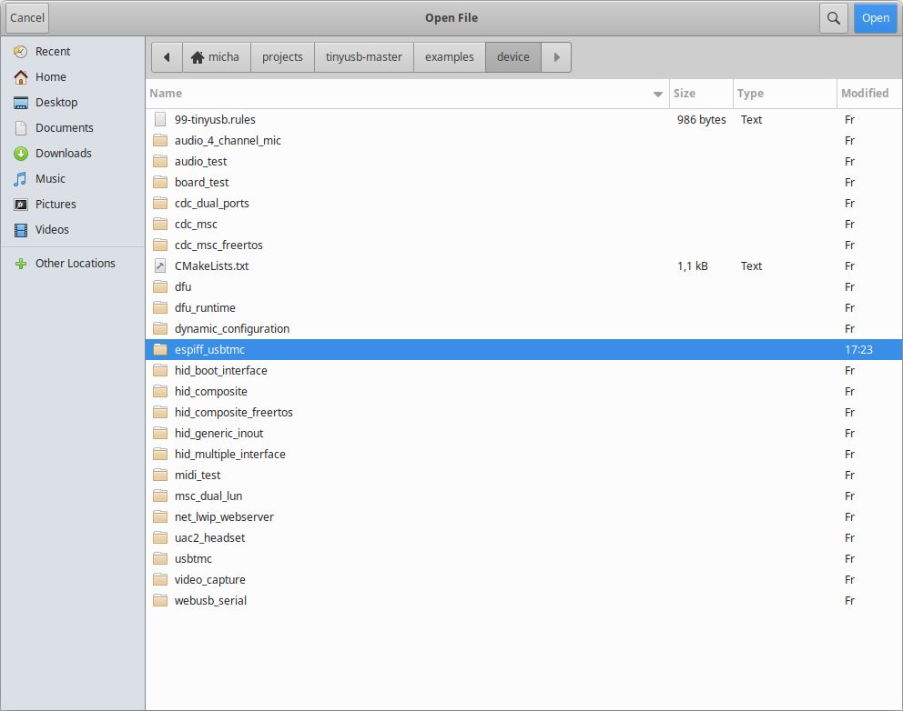
In our EsPiFF/example/usbtmc folder, we prepared a template for the EsPiFF USBTMC device. Start by downloading the official TinyUSB, create a new folder called espiff_usbtmc under ./tinyusb/examples/device/, and copy the files from ExPiFF/example/usbtmc to it.
Now we can start modifying the device names, serial number, manufacturer string, and so on.
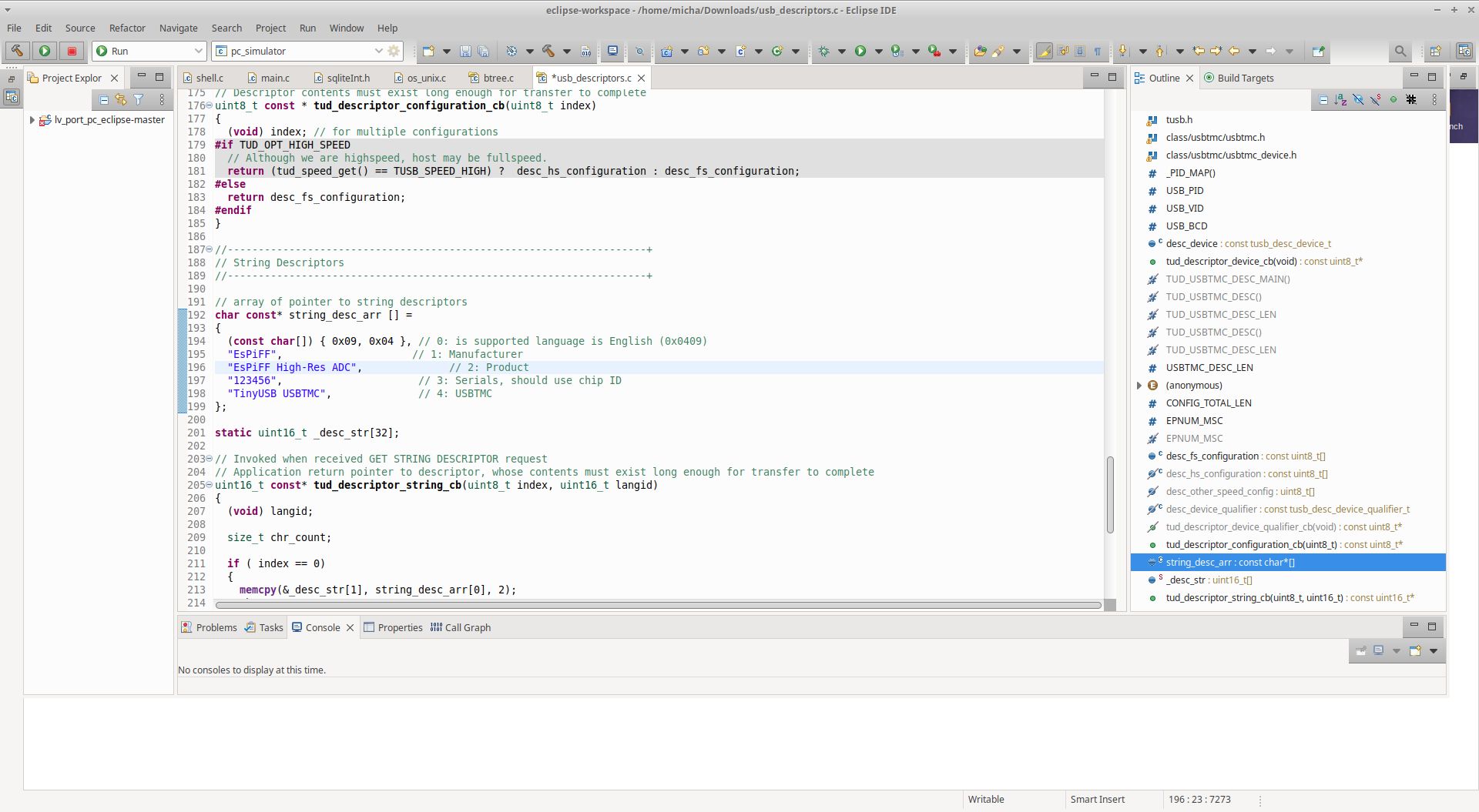
Starting at line 192 in usb_descriptors.c, you can enter these identifiers as needed.
Next, we compile and flash onto the EsPiFF, and we have functional Data Acquisition Device (DAQ) hardware with a USBTMC interface that can be controlled by LabView, Sigrock, or Octave or simply by Python.
Our DAQ reports over USB that it offers:
- Four voltage measurement channels (ADCs)
- Four voltage source channels (DACs)
- Eight bidirectional digital IOs (GPIOs)
Before we can use our DAQ, we need to implement a few HAT specific functions. Open usbtmc_app.c, and you’ll see the following placeholder functions:
// HAT specific implementation:
void gpio_setup(uint8_t ch);
void dac_setup(uint8_t ch);
void adc_setup(uint8_t ch);
uint32_t adc_get_sample(uint8_t ch);
void set_gpio_as_input(uint8_t ch);
void set_gpio_as_output(uint8_t ch);
bool is_gpio_output(uint8_t ch);
uint32_t get_DAC_value(uint8_t ch);
void dac_set_value(uint8_t ch, uint32_t new_val);
Let’s look into these. We have set up functions for ADC, DAC, and GPIOs. Because these are on the HAT, we need code from the HAT manufacturer. Most Pi HATs have code examples just for the Raspberry Pi and Arduino libraries are also available. In our example of the wave-share HAT, we can use a handy Arduino class in the source code. Let’s copy ADS126X.cpp and ADS126X.h into our ./tinyusb/examples/device/espiff_usbtmc folder, including the header file, into usbtmc_app.c and run:
ADS126X adc;
int chip_select = 5; // RP2040 pin connected to CS on ADS126X, Pi_GPIO22, physical pin 15 on RPi header
void adc_setup(uint8_t ch)
{
  adc.begin(chip_select); // setup with chip select pin
  adc.startADC1(); // start conversion on ADC1
}

uint32_t adc_get_sample(uint8_t ch)
{
   uint32_t val = 0,
switch (ch)
  {
    case 1:
      val = adc.readADC1(1,2); // read the voltage between pin 1 and 2
      break;
    case 2:
      val = adc.readADC1(3,4); // read the voltage between pin 3 and 4
      break;
    case 3:
      val = adc.readADC1(5,6); // read the voltage between pin 5 and 6
      break;
    case 4:
      val = adc.readADC1(7,8); // read the voltage between pin 7 and 8
      break;
    default:
      val = 0;
  }
  return val;
}
That’s it for the wave-share HAT! Since it does not have any DAC or GPIO, you can comment out those functions.
We will soon update the EsPiFF GitHub repo with the USBTMC example code for our analog and digital HATs. These have analog inputs with voltage and 4-20 mA, analog outputs with voltage and 4-20 mA and bi-directional digital IOs. So it will use all the above functionality.
USBTMC is an ocean of specs and details. We’ve just scratched the surface with these little reports. To hide most of the complexity, and to help EsPiFFers to quickly see results, we created the template and the instructions referenced here. But if you plan to implement not-so standard applications, be prepared to dig deeper into SCPI (a test and measurement protocol) and USBTMC.
Taking things to the next level could include using the ESP32 on the EsPiFF. If we wanted to build a USBTMC-to-Ethernet converter, the ESP32 would add the ethernet port. With Firmata, our standard ESP32 to RP2040 protocol, we can transport data between the two controllers. This could compete with the previously mentioned Agilent USBTMC-to-Ethernet by adding a GPIB HAT. But that’s a story for another week’s update.
Wishing you all a Merry Christmas,
The MDC Team