Project update 2 of 11
The Evolution of the AquaPing Design
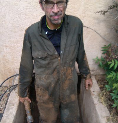
by Mike HI began thinking about water leak sensors shortly after a flooding episode at my house. A hairline crack had developed in a PVC irrigation pipe located in the crawlspace. It went undetected for six weeks and led to considerable damage and expense that included a hefty fine for excessive water usage. This photo shows me emerging from the crawlspace, having just located and repaired the leak with the help of my brother-in-law. The furnace was saved, but the floor insulation was not. About six inches of standing water had to be removed. Mold soon developed.
This unpleasant experience got me researching available remote leak detection products. It’s not clear that either of the sensing schemes for home automation would have caught this leak quickly. A contact moisture sensor must be placed in a low spot where water will eventually accumulate and pool. It is unlikely to be effective with the porous dirt floor of a crawlspace. An inline smart meter could have eventually seen the anomalous, continuous flow, although such meters may not be reliable with small leaks below 0.2 gpm.
I did some experimentation that showed the high-frequency acoustics accompanying pressurized water escaping from plumbing can propagate a significant distance in free-space – 30 ft. or more. This suggests a stand-off method of water leak detection, in which a single sensor can monitor a large open area like a crawlspace or attic. No contact with plumbing is necessary.
The fundamental idea is to collect and analyze the acoustic energy at high-frequencies (> 6 kHz). There are several reasons for this approach. Removing low frequencies makes it easier to distinguish a persistent leak signal from the background, i.e., there is better signal-to-noise. Low frequencies are where conversations occur, so using the device for eavesdropping would not be possible. An energy approach is also much simpler than unraveling a chaotic time-domain waveform as is often done in glass breakage detection.
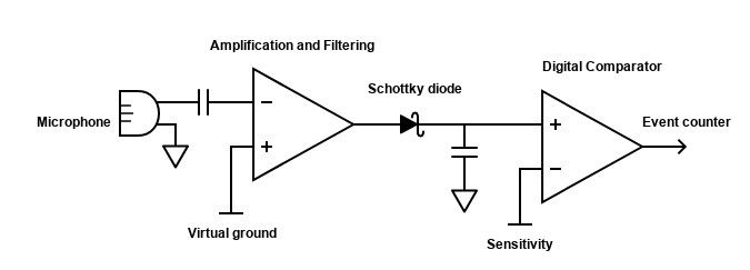
The proof-of-concept prototypes were based on the design shown in the following system diagram. The AC-coupled microphone signal is amplified, sent through an analog filter to remove low frequencies, re-amplified, then temporally integrated with a diode-capacitor peak-hold circuit. A germanium Schottky diode is used because of its lower turn-on voltage. If the captured signal is above a preset threshold, a comparator in the MCU is triggered and a potential leak signal is recorded. All the front-end electronics are pulse-biased to conserve power. Details on filtering and statistical data analysis will be the subjects of future updates.
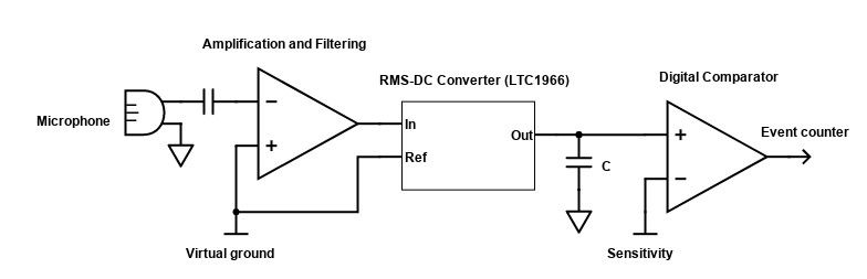
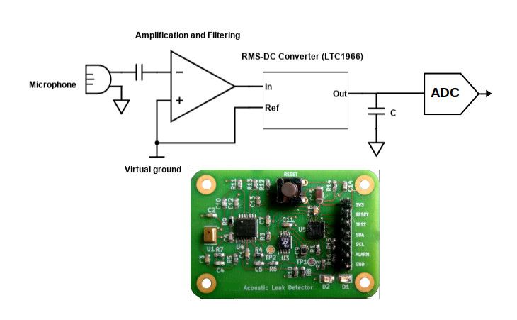
The next generation design replaced the passive peak-hold circuit with active RMS-DC conversion, which provides a true measure of the energy in the filtered analog waveform. The Analog Devices LTC1966 was used for the converter because of its 3V3 supply voltage, provision for external gating, and very low power consumption. The modified system diagram is shown below.
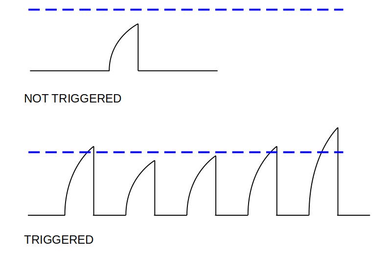
The output of the LTC1966 is time-integrated by charging the capacitor C, which produces exponential waveforms as sketched below. Peak amplitude is proportional to the acoustic energy in the filter passband. The dashed horizontal line represents the preset comparator trigger level. If the first acquisition exceeds the trigger, an additional four measurements are made in rapid succession. Analysis of these can help distinguish a leak signal from impulse noise.
At this point, this design is not really a “smart sensor” since a user/external controller is required to set a trigger level. In addition, the comparator ignores information about the sampled acoustic energy. The variability of these signals can be used to assess the stability of the environment and whether it is sufficiently quiet for weak leak signal detection.
The comparator is replaced with a 10-bit ADC in the MCU to capture the peak of the RMS-DC converter output, i.e., just at the end of the capacitor charging time. This opens up the possibility of statistical amplitude analysis to better distinguish noise and reduce the probability of false alarms. With ADC signal values, the sensor can learn about the ambient environment and no longer requires user intervention to set a threshold level. This is shown in the following modified system diagram, including an image of prototype hardware where these upgrades have been implemented.
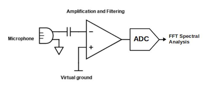
However, the LTC1966 is expensive and currently unavailable. An attractive alternative design is to eliminate this chip and instead use a higher-end MCU (MSP430FR5994); it has a built-in DSP and low-energy accelerator that can perform an FFT without CPU intervention. The present Aquaping design acquires an audio sample of duration ~ 8 ms sampled with a 12-bit ADC in the MCU. A complex FFT of the time data moves the analysis from the time-domain into the frequency-domain, where the energy in the target spectral window is recorded for statistical analysis. This current design provides higher sensitivity, greater immunity to environmental noise, better reliability, and lower probability of false alarms.
AquaPing’s design progression has involved much more than presented in this brief summary. Many of these interesting topics will be covered in forthcoming updates. I welcome your comments and questions!