Project update 8 of 15
Spectra Architecture Design
Spectra’s architecture allows it to acquire very accurate measurements, a single measurement at a time. In this update, I’ll go through the architecture design, the general flow of data and signals, and why I chose specific parts, including the main MCU, the analog multiplexers, and the Bluetooth module. The top-level design thinking that guided me was to keep the price down, whilst creating an accurate measurement system.
Analog Front End
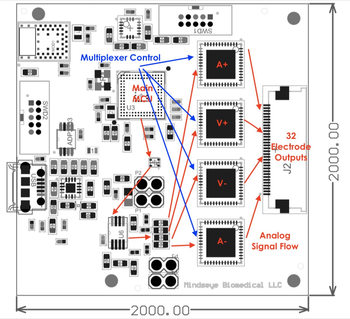
In the above block diagram, I show the emitter and receiver analog signal flows (red arrows) controlled in firmware by the main MCU. This is the analog signal created by the Analog Devices ADuCM350 integrated analog front end specially designed for high-accuracy impedance measurements. Central to its operation, this front end creates a very accurate current source. In fact, it’s so accurate that we constantly adjust it based on the temperature of the board, and it’s calibrated by an on-board resistor before every set of measurements. The front end on this chip conveniently also does the complex impedance calculation using 2048 single-frequency point discrete Fourier transform, the result of which is sent via UART to the reconstruction algorithms.
Differential Referencing
The analog sine wave signal depicted in the diagram above by the red arrows is then sent through the Analog Devices AD8226 instrumentation amplifier to turn the emit and receive into four signals, two of which are inverted for differential referencing, which is far more precise on biological mediums such as the body.
Analog Multiplexing
Each of these four signals is then sent to its own Analog Devices ADG732BCPZ analog multiplexer. These multiplexers have very low noise and very fast switching capabilities, which are critical for cleanly switching between all the electrodes.
Digital Control
Lastly, the blue lines in the above diagram are digital I/O which control the analog multiplexers. Built into the ADuCM350 is an ARM Cortex M3, which we use to control the multiplexers so that every time a measurement is made, we can switch to any set of electrodes we desire. You can see look up tables in the open source firmware that describe how to address each electrode.
Accuracy vs Cost
The above integrated analog front end, instrumentation amplifier, and analog multiplexers, all from Analog Devices, account for a large portion of the Spectra bill of materials, and for good reason - they are exactly what make Spectra reliably accurate which is very important in an EIT system. Moreover, this architecture is orders of magnitude less expensive than using a full specialized EEG system with separate current sources, such as is often found in labs, as well as being small and portable. It also has plenty of calibration documentation and examples which help you know you are measuring what you think your are measuring!
Another advantage of this system it yields phase information between emit and receive signals, thanks to the very precise clock connected to the integrated analog front end. Phase measurements are another valuable source of information that can be used in the image reconstructions, though I am currently using only signal magnitude.
Bluetooth Connectivity
I added the Rigado BMD-350 Bluetooth module to make Spectra portable. Between wireless connectivity and running off a lithium ion battery, you can better isolate Spectra from electrical noise. I chose the Rigado module because it is small, FCC pre-certified, and runs on a Nordic SoC. These factors are pretty much the key to my heart when it comes to selecting Bluetooth modules. I’m a particularly big fan of Nordic because their SoC’s come with great support, an SDK with working and supported examples, and an active forum.
In the distant past, I tried another Bluetooth module, the brand of which shall remain anonymous, and it simply wasn’t well supported, which made development much harder, so kudos to Nordic for making such an accessible ecosystem. Rigado has taken a clever path with this module by making it so small and versatile and easy to use.
On top of this, Adafruit has created a library for your laptop to stream data off through a Python interface. This library is pretty good, though is still undergoing frequent updates. Whilst trying to integrate it into the OpenEIT dashboard, I realised that it just couldn’t run with multiple threads, which is critical if you have a GUI for displaying streamed data in real-time. Happily, the library is open source, so I made a patch to enable multithreading.
Putting It All Together
The subsystems described above, plus some I haven’t described yet, combine on a single PCB to form the basis of the entire system. Check out this 3D diagram of the Spectra PCB:
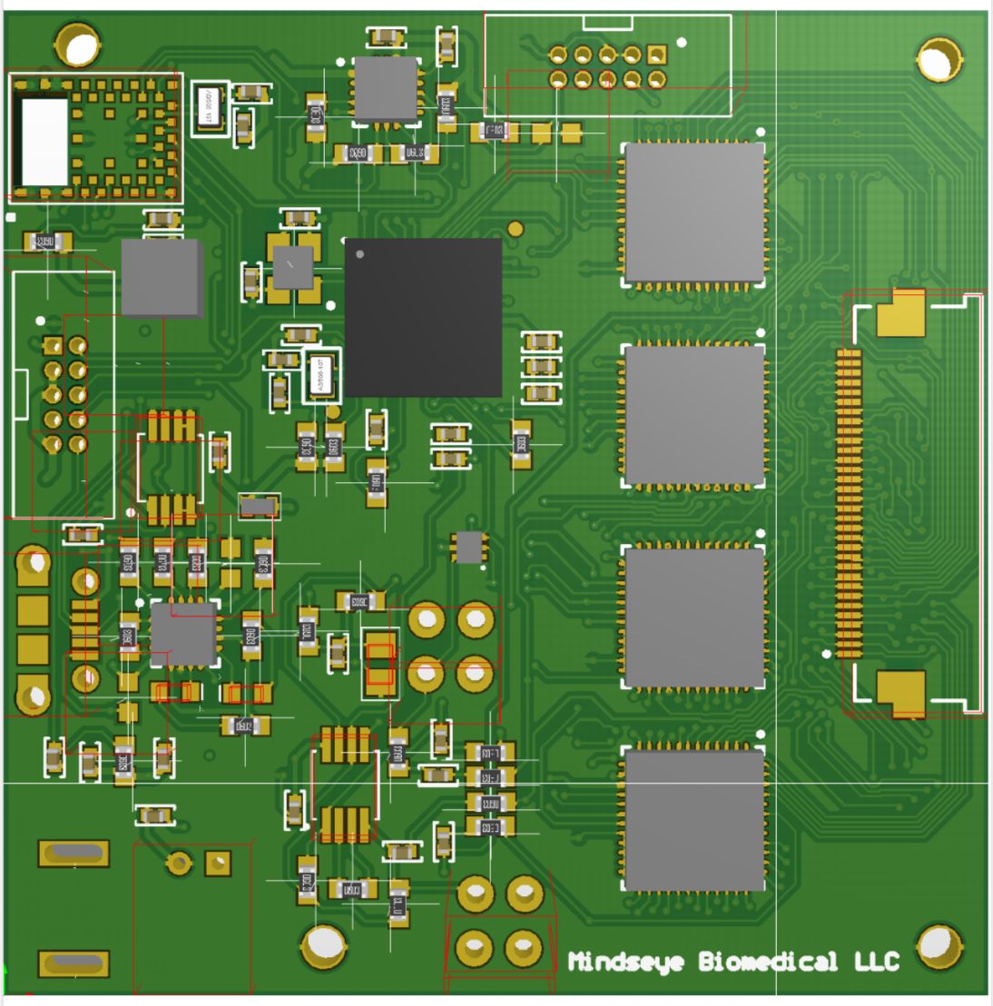
As you can see, this project is pretty detailed and has been a learning process to get it to where it is today. I hope it also becomes the foundation for other open source medical imaging projects - we need more of them!
Thanks again if you’ve supported the Spectra campaign. If you haven’t yet, now is a great time - I’d love your support helping us reach our goal!