Project update 2 of 13
A Technical Walkthrough
by MNT ResearchFirst of all, thank you so much for supporting our campaign and backing MNT Pocket Reform! The response so far has been extremely positive and we are delighted that so many people are interested in our little laptop. We can’t wait to get Pocket Reforms into your hands!
Until then, we are publishing a series of articles that highlight specific aspects of MNT Pocket Reform in depth. The first one is written by Lukas F. Hartmann, who is responsible for the electronics, and it is a technical walkthrough that explains how the Pocket Reform hardware is structured internally. The article is especially geared towards people with an interest in electronics, but can hopefully provide everyone with some insight into how the device actually works.
Two Halves
Mechanically, MNT Pocket Reform is split into two halves: top and bottom. The top half contains the actual computer and the display. That’s also why the ports are located at the right side of the top half. The bottom part houses the keyboard/trackball module, and below it, the two batteries and the charger board.
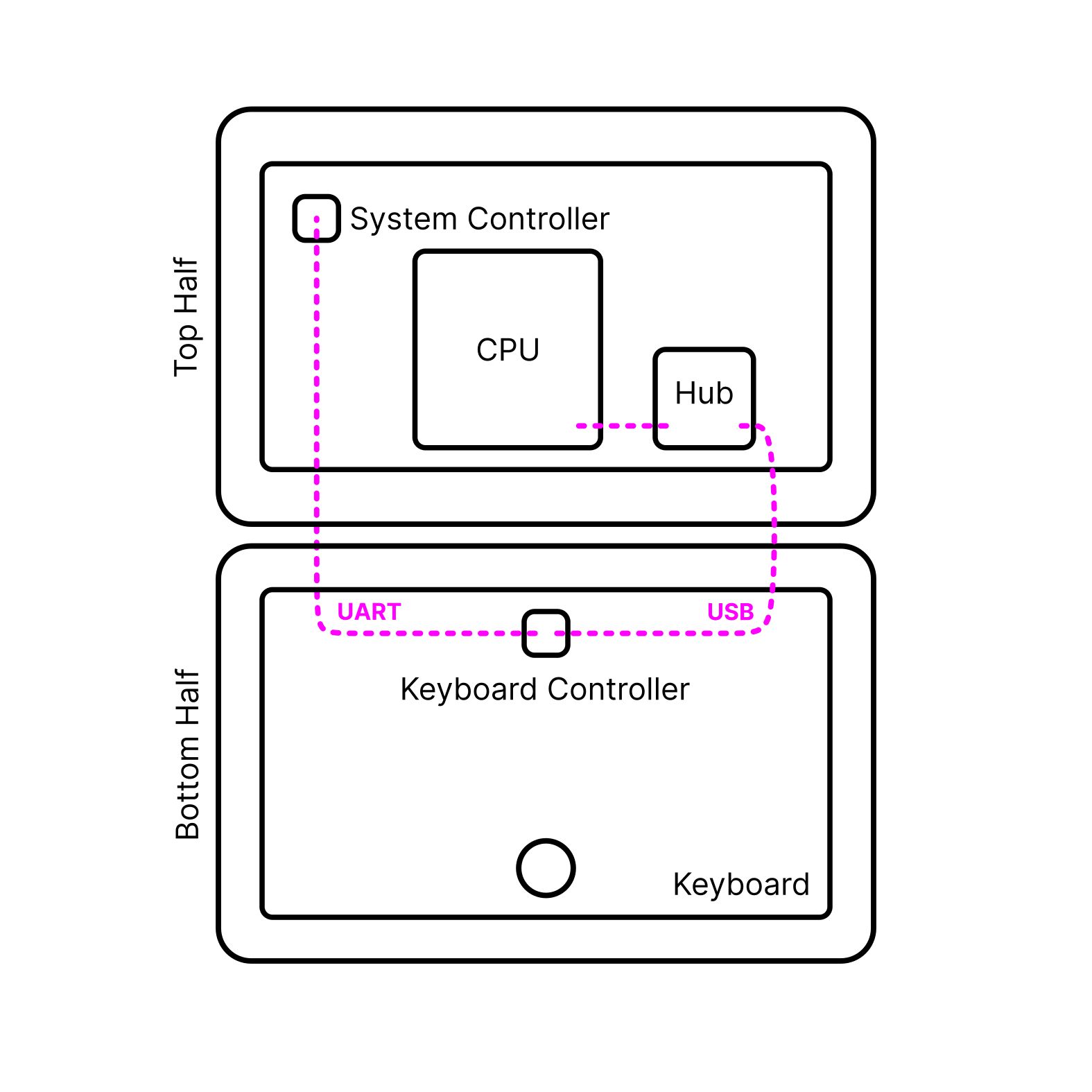
How are the two halves communicating? In the original MNT Reform 13" laptop, I wanted the keyboard (and its separate OLED display) to be a direct user interface to the motherboard’s system controller and in turn, the power system—independently from the core computer part of the system. I continued the same approach in Pocket Reform. This way, you can always directly control the core system’s power and check on the batteries and charging level, even when the CPU is off. This architecture makes it easier to bring up new CPU modules or operating systems that then don’t have to care about these details.
Technically, this works by decoupling the system control from the USB functionality of the input device. While in MNT Reform the keyboard and pointing device were two separate modules, the keyboard and trackball are combined into a single unified module in Pocket Reform. This unified module talks to the motherboard’s system controller via a dedicated UART and is always supplied with 3.3V standby power. It has a secondary connector for its USB function. This USB line is routed to the CPU module via a USB hub on the motherboard, and it is only active when the CPU itself is powered and active.
Input Module
The input module is powered by a RP2040 microcontroller (a dual-core Cortex-M0 chip with realtime I/O capabilities made by Raspberry Pi). The RP2040 scans the keyboard matrix (using GPIOs) and the trackball’s motion (over I2C) and draws a little UI on the monochrome OLED above the keyboard. The USB HID functionality is provided by the TinyUSB library. It also uses the special PIO unit to generate the data protocol that the RGB backlight’s LEDs speak. Because the trackball and keyboard are unified, we can do tricks like smoothly control the keyboard backlight’s hue and brightness using the trackball.
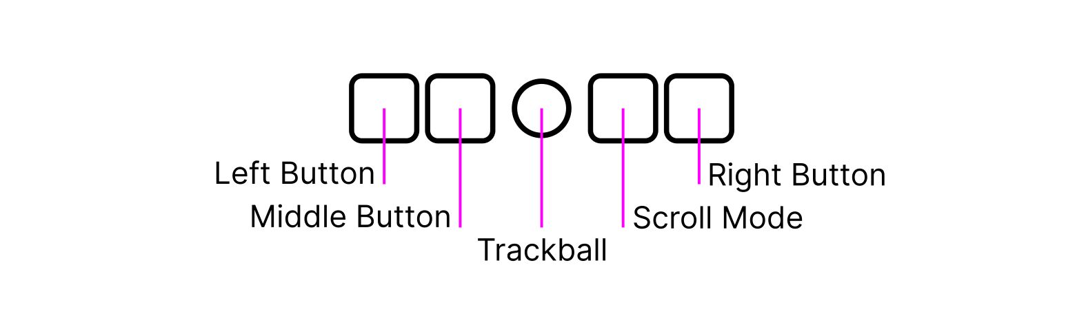
Speaking of the trackball: it has its own four keys that look identical to the keyboard’s keys. Three of them act as left, middle and right mouse buttons. The fourth key enters scroll (or wheel) mode, so you can use the ball to scroll in documents or on websites in two dimensions. The trackball reuses the same optical sensor PCB and interface from MNT Reform, but has a smaller, 3D printed cup with steel bearing contacts and a 15mm diameter POM (Acetal) ball.
The input module can also be controlled by raw USB HID commands from the Linux side, which means you can draw anything from notifications to animations on the OLED display, or make individual keys blink in any color. The keyboard’s backlight is essentially an RGB bitmap that you can play with.
Batteries and Power Delivery
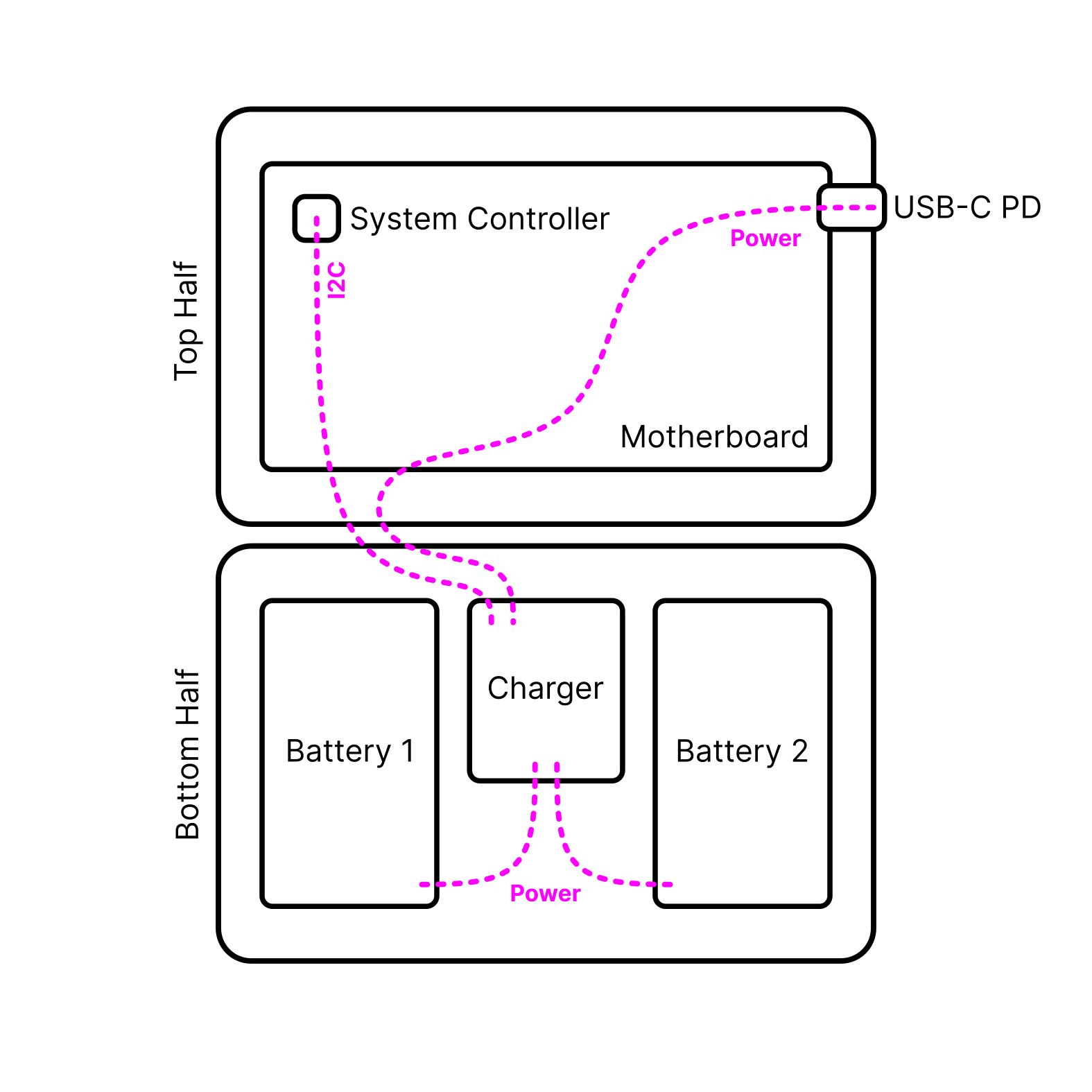
The bottom half is not only about input. Underneath the keyboard live two LiPo battery cells with 606090 form factor. In their middle: the charger board. This little PCB mainly contains two chips: one is a fuel gauge with battery protection (MAX17320G20+), and one is the actual charger, the MPS MP2762A. These chips are decoupled from the motherboard to allow for future flexibility in terms of battery architectures and chemistries, and to allow both the motherboard and the charger to be reused in other contexts.
The interface between charger and mainboard is a 9-pin JST PH connector with the following pinout (subject to change):
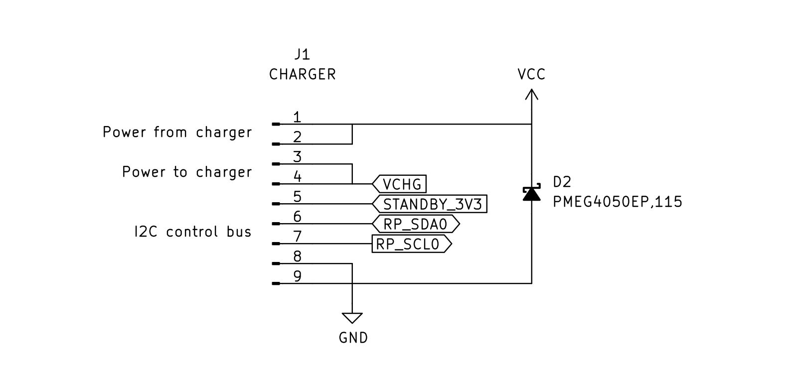
As you can see, "raw power" from an external source—in this case, from a USB-PD charger—enters the charging board, and system power, sourced and regulated by the MPS from either the batteries or the external input, comes out and goes back to the motherboard. The I2C bus is for communication with the charger and protector chips.
Motherboard
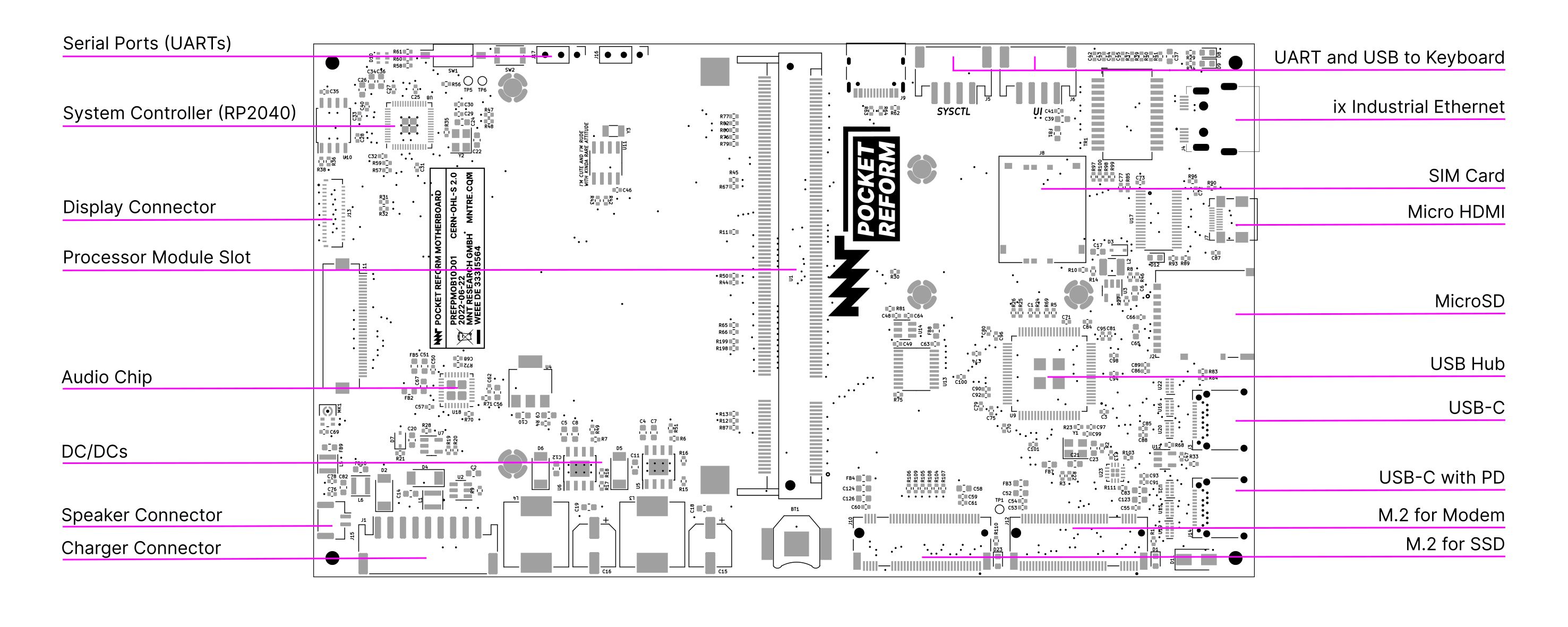
The motherboard has several jobs. Lets start with power: the motherboard contains another RP2040 MCU (in addition to the one in the keyboard/trackball). This one is called the System Controller. It listens to commands from the keyboard, which can instruct it to turn the main CPU’s power on and off, for example. But it also keeps track of the charger’s status, and in turn the batteries’ health. Both the CPU and the keyboard can track these details, and that’s how the charging status can be displayed on the OLED while the CPU is off.
The system controller also implements the high level state machine for the USB-C Power Delivery handling. The lowest levels of the PD protocol are handled in a dedicated chip on the motherboard, the Onsemi FUSB302B, which connect’s to the first USB-C ports’ CC lines. The system controller can also decide to switch that USB-C port’s power line to output instead of input (or Source instead of Sink in PD parlance). This way, you can connect a USB device instead of a charger to the port and have it powered by Pocket Reform.
Speaking of, there’s lots of USB action going on: two USB-C ports that both have USB 2.0 and 3.0 signalling, plus an internal USB port for the input devices, and another one integrated in the B-Key M.2 slot for the optional cellular modem. All of these USB signals are multiplexed by the TI TUSB8040 USB hub on the motherboard, which in turn is connected to USB 3.0+2.0 root ports of the CPU module.
Storage
Besides eMMC flash, which is located on the CPU module itself, the motherboard has a MicroSD card slot and an M-Key M.2 slot. The latter carries a PCIe lane from the CPU module. The intended purpose is to drive an SSD NVMe, but it could theoretically be used for other expansions (including custom ones) that can benefit from the relatively high PCIe bandwidth.
Ethernet
To support direct connectivity to wired networks, I wanted to include Ethernet, but not have to worry about the large volume required by a typical RJ-45 jack. There is an underused alternative introduced by Harting: the ix Industrial connector type A. It has space for the same signal pairs that Ethernet requires and features a robust and clicky locking mechanism, but it occupies a lot less space. Visually it reminds a bit of Firewire or the Gameboy link connector. Passive cables adapting from ix to RJ-45 are made by several companies. The ix jack does not contain its own magnetics, so I selected a compact transformer chip for decoupling the Ethernet signals.
Display
Unlike in the original MNT Reform, the JDI LT070ME050 display panel in Pocket Reform does not speak eDP (embedded display port) but MIPI-DSI, which is common in mobile devices. Most ARM SOCs—including the i.MX8MPlus—have native MIPI-DSI output, so theoretically things should "just work". There are no standard connectors or pinouts in DSI land, though, so in our case the motherboard has an input for the DSI signals coming from the CPU module, and it combines these signals with power, reset and enable signals that have to be just right for the specific display. Documentation on these panels is spotty, so figuring out how this works and how the init sequence has to be subtly different from what the existing Linux driver says was quite painful.
HDMI, on the other hand, was straightforward. To save space among the connectors, and because adapters are common (for example, for Raspberry Pis and digital cameras), I went with Micro HDMI. The motherboard routes the required signals from the CPU module and has an EMI protection chip that we often use in products with HDMI ports. On the i.MX8MPlus, no firmware blob is required for the HDMI output.
Audio
I wanted to keep audio simple and modern. I expect people to have bluetooth earbuds or be ok with using a small USB-C sound card dongle to break out TRRS jacks. On the other hand, my colleague Anri convinced me that the device should have a speaker. And a really nice speaker it has: The CUI CES-361811-18PM-67. This time, it’s mono, which I think is totally fine for a small device—but it sounds really nice and (if required) loud due to its self-contained acoustic housing. For the audio chip I went with TI TLV320AIC3100 which integrates a speaker driver and is connected to the main processor using I2S and I2C protocols.
Case and Reusable Parts
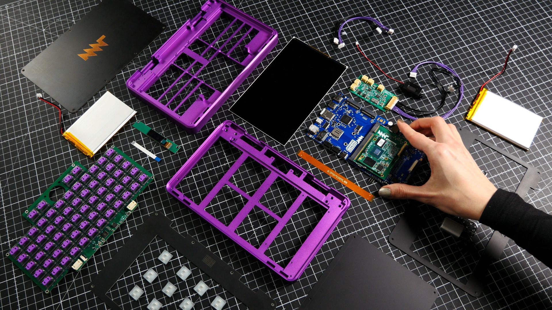
The two halves, top and bottom, are aluminum parts CNC milled from a single block each. These were designed by Ana Dantas. Each half is closed by two plates that can be easily removed by removing some M2 screws. The four plates are actually printed circuit boards: the inner plates (bezels for the display and keyboard/trackball) are made from black core material, so their milled borders don’t distract too much visually (regular FR-4 is usually bright on the inside).
The use of PCBs as a case material is inspired by the DIY modular synthesizer scene and projects like the Precursor. The back plate PCB also acts as a heatsink: It has exposed copper on the inside. This copper surface is connected with thermal pads to the main processor. Because the plates are PCBs, and they have some extra space, you can make your own mods including custom circuits, ports or LEDs, including your own PCB art.
The hinges are the same SMS-ZZ-219 hinges from Smooth that we use in the MNT Reform laptop, but tuned for less torque. We still have a lot of them in stock, and we like to reuse components wherever it makes sense. There are also some other parts shared with Pocket Reform’s bigger sibling: The OLED PCB, the Trackball Sensor PCB and last but not least, the CPU Modules are compatible—if they have MIPI-DSI output for the display.
Conclusion
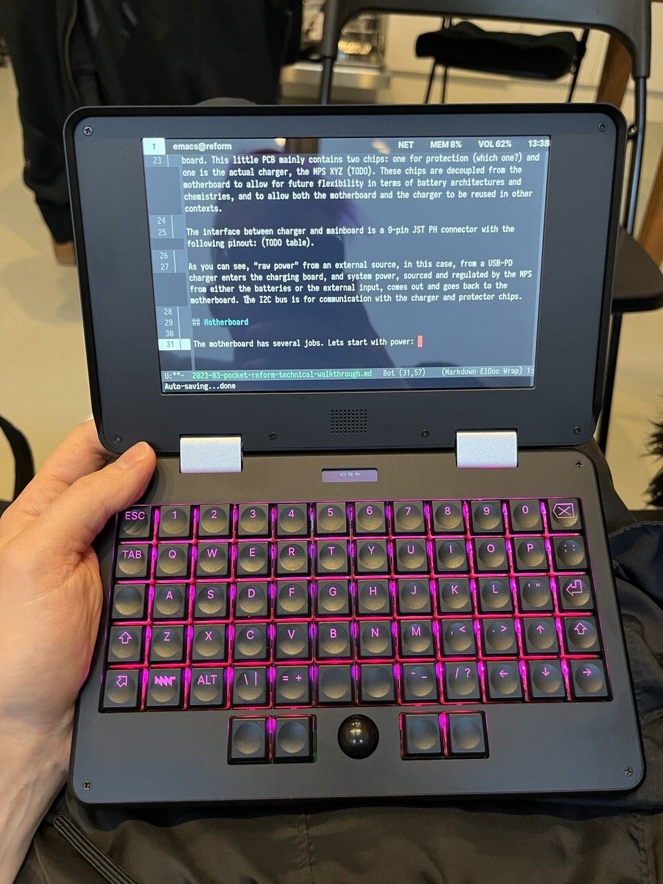
I’ve been using my personal MNT Pocket Reform for a few months now (in various alpha and beta states) and already got used to touch-typing on the small ortholinear keyboard. As an experiment, I wrote the bulk of this article on the device using Emacs and the linear Kailh Choc Pro Red Switches. It worked well—the distraction free interface and relatively small screen helped me focus.
My team and I are excitedly looking forward to the next weeks of the campaign with you!