Project update 8 of 9
Production Status, New User Manual, and Unexpected Improvements
by Colin O'FlynnWelcome to our third post-campaign update! In this update, we’ll talk about:
- Shipping & production updates
- We wrote a user manual!
- Unexpected Husky improvements
- Update on our suspicious regulator
- More Artix A35 target testing
Shipping & Production Update
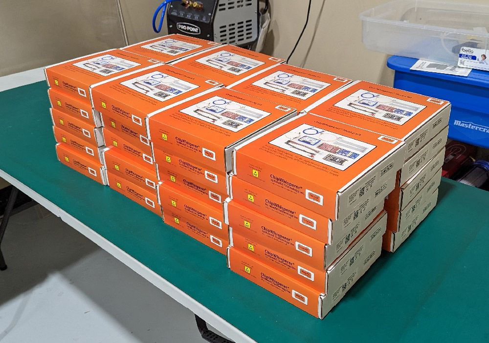
We’re still working on getting everything to you. We’ve already shipped the STM32F sockets to Mouser (see last update for photo of that).
The main Husky units will ship in batches, in part due to the physical size of the order, but also because we tend to test and package them in batches anyway.
The first batch is going out shortly. We’re still waiting on the second part of our production run to get the balance of boards, but we used this first batch to tune our testing and packaging plans.
Please ensure your shipping address is accurate in your Crowd Supply account as we prepare for this!
We also got our sample of 10 units from the full production run, which was the last major hurdle to a complete on-time delivery. Happily everything works as expected. The only change we’ll have to make is that we found out some of the parameters we put in our tutorials for the voltage glitching tutorials don’t work reliably with both production runs. This is because of minor variations in the MOSFET itself - it’s the exact same part number, but a different date code. The shape of the glitch that comes out of the MOSFET looks slightly different between the two date codes. So when you get your ChipWhisperer-Husky you might notice a "REVB" marking on it. We’ll use this in the tutorials to load optimal settings for the MOSFET on your board.
We’ve already run into this sort of variation with the ChipWhisperer-Lite, but it’s a little more pronounced with the ATSAM4S2AA target we use in the ChipWhisperer-Husky than the STM32F3 target in the ChipWhisperer-Lite. The ATSAM4S2AA runs at 1.2V, so we found it’s more sensitive to changes in the glitch parameters than the 3.3V core voltage the STM32F3 runs at.
We’ll share what those look like in the next update to give you a better idea! But the important news is both work just as well for the task at hand, simply if you want to "cheat" and load known-good settings we need to have two different default settings. Loading the known-good settings saves you several hours of running the characterization code - it may seem silly, but we think it’s much more exciting when you’re getting started when you see glitches quickly! Once you start exploring the space a little more you can run the full characterization (a task you’ll need to do anyway when working with other targets).
User Manual
We had always hoped to get this done, but we never included it in the promised kit, since we weren’t sure there would be time. We managed to pull together the details to make something we think will really make the kit even more useful:
We’ll post the updated manual online shortly, so you can start looking at that before the unit arrives. This manual is more of an introduction to how you use the Husky & what power analysis & fault injection is than a classic user manual. We always wanted to have this available, since it makes getting started possible for someone who is simply curious about the entire field.
With the Husky itself still being under development, we avoided putting any "likely to change" details in the manual! Of course, improvements still can make the manual slightly inaccurate, like the following one.
ChipWhisperer-Husky Feature Improvements
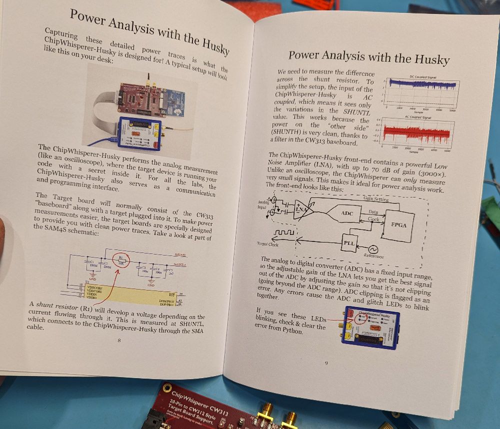
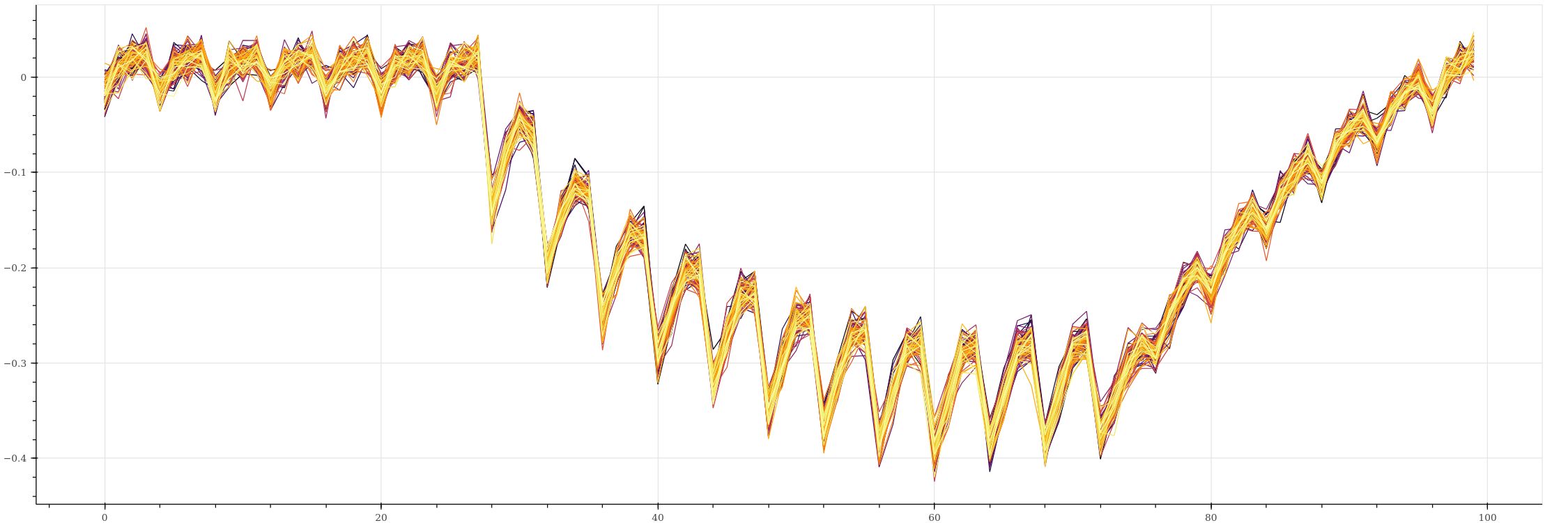
One of the cool features of the ChipWhisperer-Husky is it can actually trigger on a pattern in the analog waveform. This is helpful with power analysis & fault injection, since these waveforms of the power usage let you understand when the device is running certain operations.
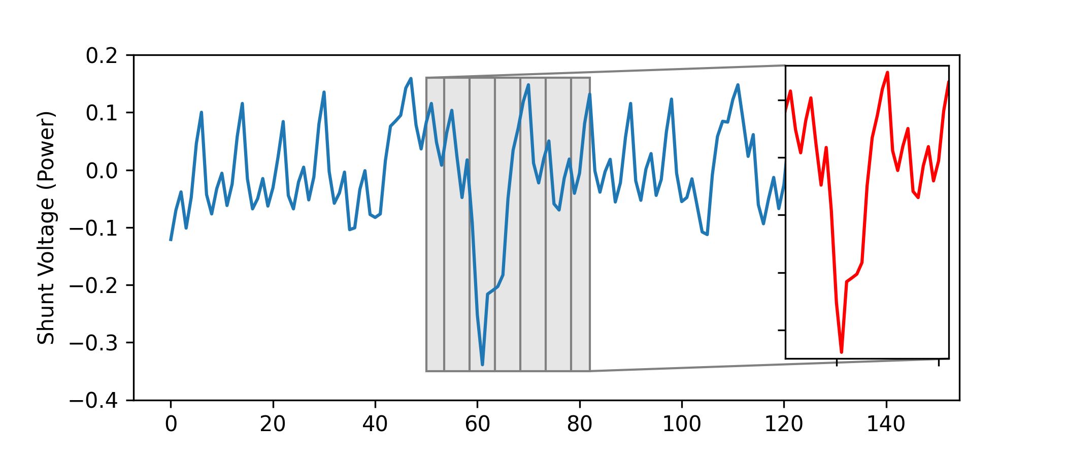
In the above image, the waveform pattern (in red) is 32 samples long, which was the maximum size we could fit in the current FPGA. This same image is in the user manual, since it accurately reflected the SAD match logic as of a week ago.
While in a recent commit, J-P managed to increase this four times with some FPGA refactoring, meaning the pattern can now be 128 samples long. This also matches what we had in the ChipWhisperer-Pro!
This works up to the 200 MS/s of the ADC, so you can use this both with our normal synchronous capture, but also asynchronously. This feature alone can be helpful even if you’re just triggering other equipment, so this expansion makes the ChipWhisperer-Husky even more useful.
Supply Chain Update on 1.2 V Regulator
On the last update, we had some detail about a suspicious supply-chain problem. It turned out we fell victim to one of the classic blunders. The first board we tested did have a defective voltage regulator. But of course there is some non-zero failure rate of any part mounted on the board (which is why we try to ensure everything gets tested before shipping).
Because the part looked different, we assumed it must be a problem with the lot, being very sensitive to supply-chain anomalies these past couple of years. We didn’t consider that we were on the receiving end of that very small failure percentage of the legitimate parts.
But the manufacture looks to have simply changed the markings on the part. We use the same part on our CW308 board, and the parts looked identical to that board. So while the parts looked different than the current version, we could confirm with a known-good previous version they were identical.
The distributor also confirmed the origin of them, so we had a lot more confidence that it was just a fluke the first board we tested was defective, and the defective part was one that looked different from our current stock.
To close this out, we ran a stress test on the 1.2 V regulator. Here we’re running it in a 80C ambient chamber, with around a 200 mA load on the output:
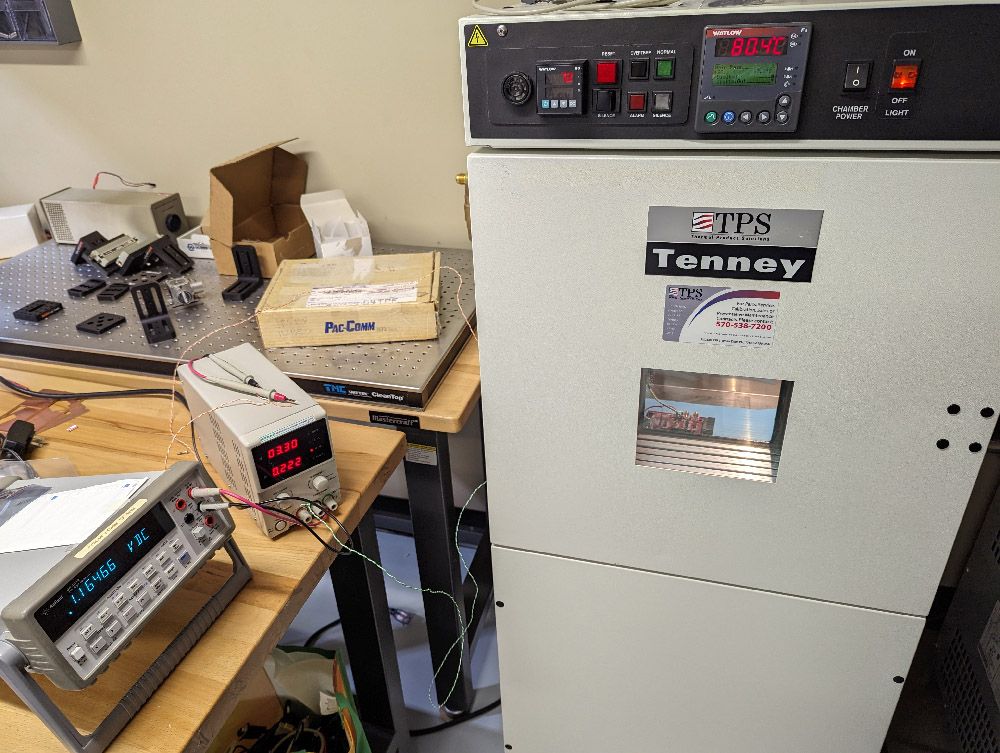
The 40 mV drop on the output is partially from the fact we had the load part-way in the measurement cable, so don’t read too much into the voltage drop. Either way, it’s still well within spec (1.140 V to 1.260 V over 0°C to 125°C junction temperature & 10 to 800 mA). More importantly, this output was very stable as we ramped the temperature, dropping less than 10 mV.
This helped with our production, since we didn’t need to do the regulator swap.
More Artix Target Testing
In the previous update I showed the FPGA Artix target. This time, J-P has been running some various tests on it. First, the all-important test of running hardware AES showed a reasonable power trace that can be broken in about 2000 traces using a standard correlation power analysis (CPA) attack:
He also did some tests to check if the shunt resistance was too large, and causing too much drop-out. It turns out, it is - we’ll make some modifications to the board to give better support for larger designs.
The following table shows a rather nice scaling of how much logic gets put into the design and when the FPGA dropped out due to the excessive voltage drop on the shunt resistor causing the core voltage to droop.
| AES Cores | Utilization | Maximum Frequency (excessive drop) |
|---|---|---|
| 1 | 12 % | 80 MHz |
| 4 | 44 % | 40 MHz one core, 25 MHz four cores |
| 8 | 87 % | 20 MHz one core, 12 MHz eight cores |
As the logic packed into the FPGA increases, so does its power consumption, and thus the drop across the shunt resistor. You can see this also scales with frequency, which is also expected, as higher frequencies cause higher power consumption.
The CW313 baseboard includes a provision to "shunt" the jumper (short it out), which we also tested. When this is used, the 8-core AES could run up to around 80 MHz, so even with the current revision we also confirmed our back-up plan of using the bypass jumper would succeed.
Interestingly, with the bypass jumper mounted, we still see some reasonable power traces due to the inductance of the lines along with (assumed) small resistance the jumper presents:
You’ll notice the "larger shift" isn’t present from the AES kicking on & causing the larger power droop. This can be helpful when you’re trying to implement a larger design, so even in the final version we may recommend testing with the shunt resistor bypassed.
There will be another update with the final version of this board, but in the mean-time, we can continue development with this one, as have proved it provides enough functionality for our power-analysis results to succeed.