Project update 8 of 11
SwarmDrive Haptic Feedback Experiments
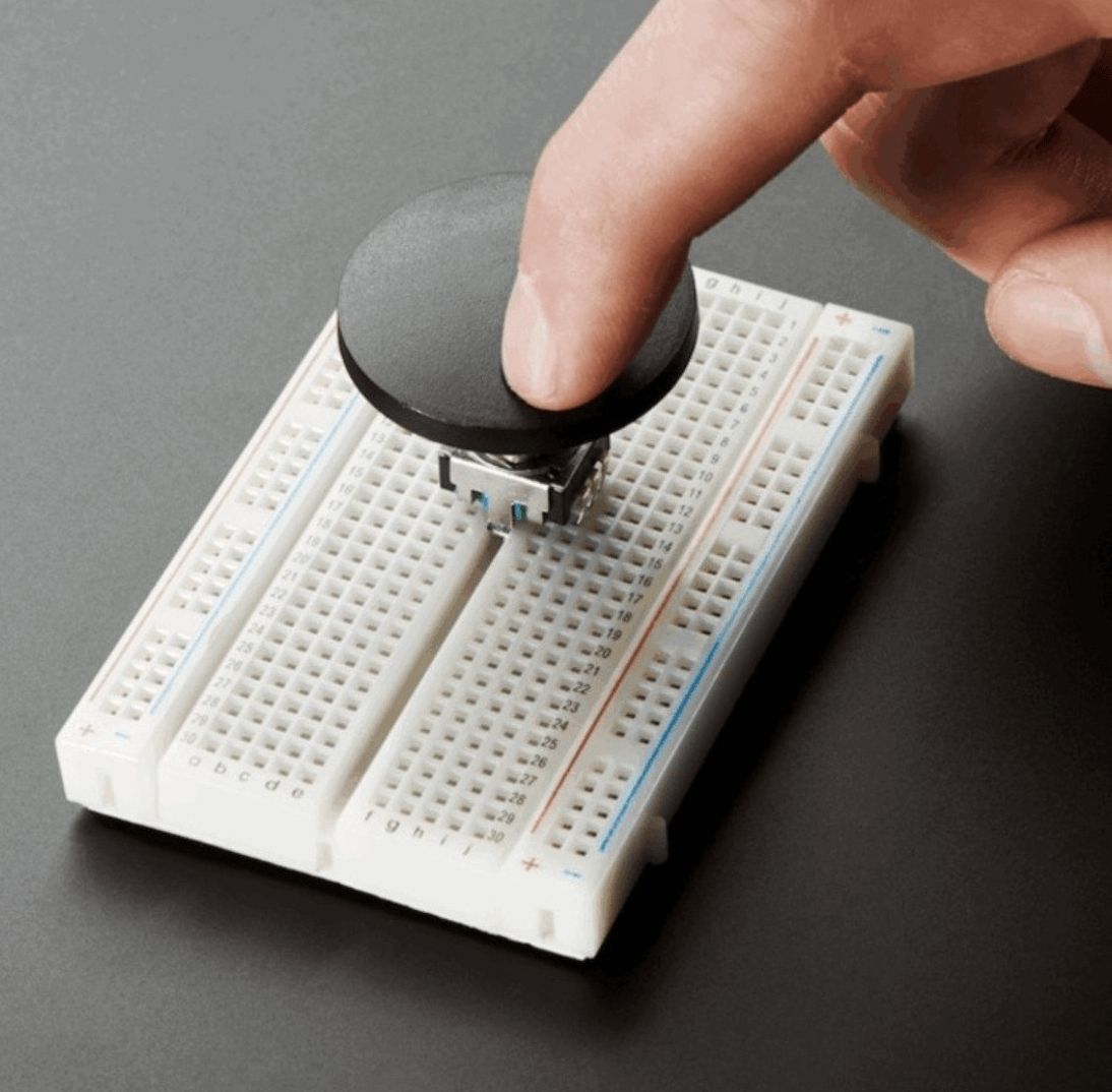
by Majodi PloegmakersThis time I would like to dive into the exciting domain of haptic feedback using electric motors. Imagine a Rotary Encoder used in many projects or devices as an endless knob to change a setting or to navigate through a menu. Mostly these devices are built using some sort of mechanical spring mechanism to give tactile feedback when rotating. The characteristics of this feedback cannot be changed. However, if you would emulate the feedback response of such a rotary encoder using an electric motor, a whole new world of possibilities opens up. Now the tactile or kinesthetic feedback (also known as haptic feedback) can be controlled.
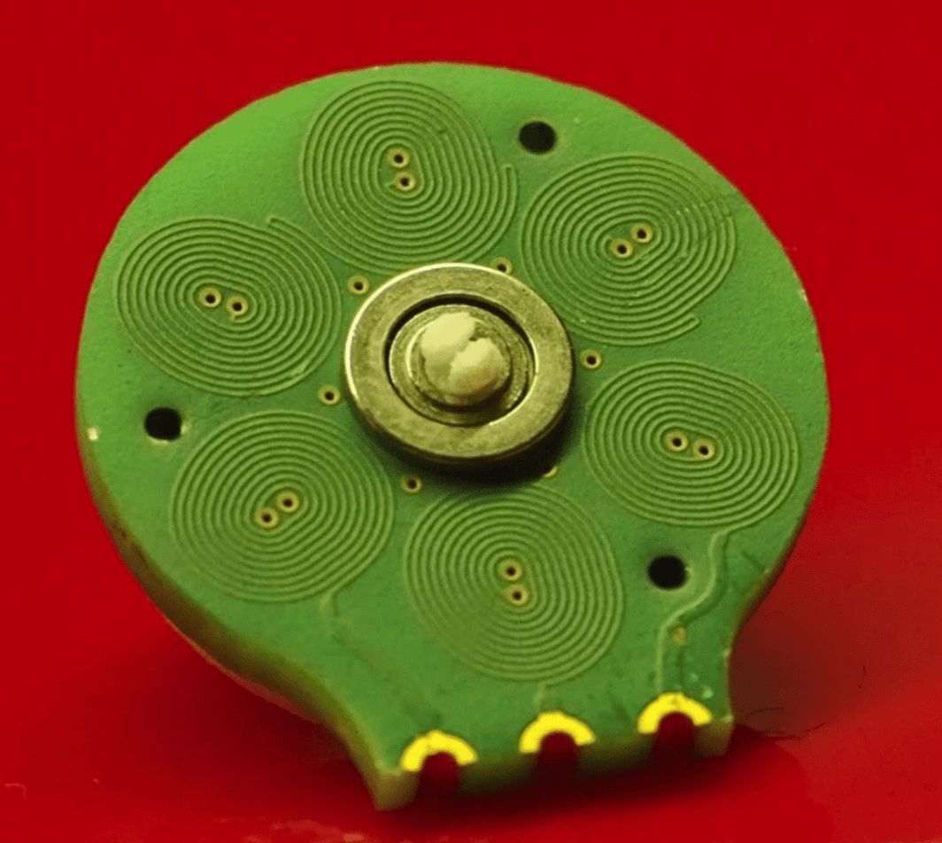
PCB motor
The motor used here doesn’t have to drive a heavy load. It just has to give the user some sensation while using it. So, wouldn’t that be a perfect use case for a PCB motor? I think it would. Carl Bugeja did some pretty interesting research on PCB motors. He mostly used very small instances of it, I think that a somewhat bigger model would be more suitable here.
The idea presented here is certainly not new. There are some companies that already have such products and there are some makers experimenting with the concept. SwarmDrive could be a handy tool to get started with this. So, I created a very basic haptic class for SwarmDrive to have an easy start.
Haptic class library
After experimenting with it for a few days I have to say that it is not super easy to get the results I had in mind. I think part of it is caused by the type of motor I was using but at the end I got some reasonable results. My hopes were to get to the level of writing code for easing functions like being used for animations. But to get some basic reliable feedback functionality working turned out to be difficult enough already.
At the most basic level I wanted to control the “notches” you experience with a mechanical rotary encoder. I wanted to be able to define the resolution (number of notches) and the feel. By feel I mean the feeling of resistance, click-through acceleration and/or stickiness. Input parameters needed for this are at least angle, speed and direction in which the knob is turned. To measure or sample these parameters, a timer is used. It quickly becomes clear that there are many factors at play here. These include the motor characteristics, the sensor accuracy and things like timing issues. This makes it hard to predict the actual outcome when experimenting with certain expectations in mind.
After having established some fairly reliable input, the next step is to produce feedback effects. In other words, how to inject movement (in a subtle way) of the motor while the user is spinning the knob. We have an arsenal of possible control features at our disposal like direction, power, torque, frequency etc. All of which can be used to emulate a simple click, buzz, resistance or even the kinetic energy of a high mass knob that continues to spin after the user’s turning force has stopped. This is what I intended to use as ingredients for the easing functions. I ended up with some crude applications of these parameters in a fixed manner. By the way, I used a sine pattern for this example (not the Space Vector LU table used earlier) as I think it has a more pronounced shape and thereby a more pronounced effect. If that is true, I’m not sure yet.
The code
The main parts here are the timer callback for sampling the user action of spinning the knob, a handler function for generating some feedback effect and the main loop where this handler is triggered at the right moment. For the triggering at multiple angles a modulus window is used. So, when having 360 degrees it is easy to check if a certain position (window) is reached by using a modulus check (checking the remainder of a division). However, the size of this trigger window needs to be flexible and adjusted for speed of which the knob is turned. Otherwise, the trigger is fired multiple times (still in the same window and thus oscillating) or not at all (window not detected). Luckily, we have the speed parameter for this.
So, the triggering code looks like this:
    void mainTask(void *arg) {
        HRE hre((motorConfig *) arg);
        int lastAngle = 0;
        int mod = 0;
        int speed = 0;
        int window = 0;
        while(1) {
    	    lastAngle = hre.getAngle();
    	    mod = lastAngle%40;
    	    speed = hre.getSpeed();
    	    window = (speed / 100) * 2;
    	    window = window < 7 ? 7 : window;
    	    window = window > 15 ? 15 : window;
    	    if ((mod > 0) && (mod < window)) {
    		    hre.handle(lastAngle);
    	    }
    	    vTaskDelay(1);
        }
    }
Sampling
I experimented with the timer callback function a lot to get accurate speed and direction values. When working with single sensor readings we have to take the sensor zero cross-over into account. But for the speed, single samples were way to inaccurate so I ended up using averaging 100 samples at a frequency of 3000 Hz.
For the handler function (which generates the effect the user experiences when passing a window) I first tried to use a window with an entering zone and an exit zone. And although I did get some reasonable results at the end, I skipped this concept and just use a very crude way now. This involves nothing more than just "moving" the knob outside the window. Not in an elegant way but just by using a commutation loop until the exit is confirmed. The main struggle here was that the motor I used is not always as predictable. So, a forced “eviction” until confirmed worked better than the earlier concept with the enter/exit zones.
The code:
    void  HRE::handle(int angle) {
        if (_dir == 1) {
    	    while(abs(getAngle() - angle) < 5){
    		    commutate(_lastStep-25);
    		    ets_delay_us(SST); // let it settle
    	    }
        } else {
    	    while(abs(angle - getAngle()) < 5){
    		    commutate(_lastStep+25);
    		    ets_delay_us(SST); // let it settle
    	    }
        }
        mcpwm_set_duty(MCPWM_UNIT_0, _coil0, MCPWM_OPR_A, 0);
        mcpwm_set_duty(MCPWM_UNIT_0, _coil1, MCPWM_OPR_A, 0);
        mcpwm_set_duty(MCPWM_UNIT_0, _coil2, MCPWM_OPR_A, 0);
    }
(code can be found at Github)
The result
The result of it all is a resemblance of a mechanical rotary encoder where you feel the clicks. But a lot of improvement is needed here to make it more accurate and more similar to its mechanical counterpart. After that, maybe more interesting effects will be the next step. I experimented with short, high frequency bursts and that does make it more interesting. You could imagine a knob used for CAD work where you feel features of the drawing you are working on.
Anyway, the possible applications for a device using these concepts are endless. The challenge is to get it working accurate and reliable. The given code here is just a basic start. My hopes are that SwarmDrive can serve as an easy prototyping tool to build more sophisticated designs.
Until next time,
Majodi