Project update 3 of 13
How to use CircuitBrains
by Kevin NThere are a couple of steps that are important to making use of CircuitBrains. They are as follows:
Choose a USB port and work it into your design
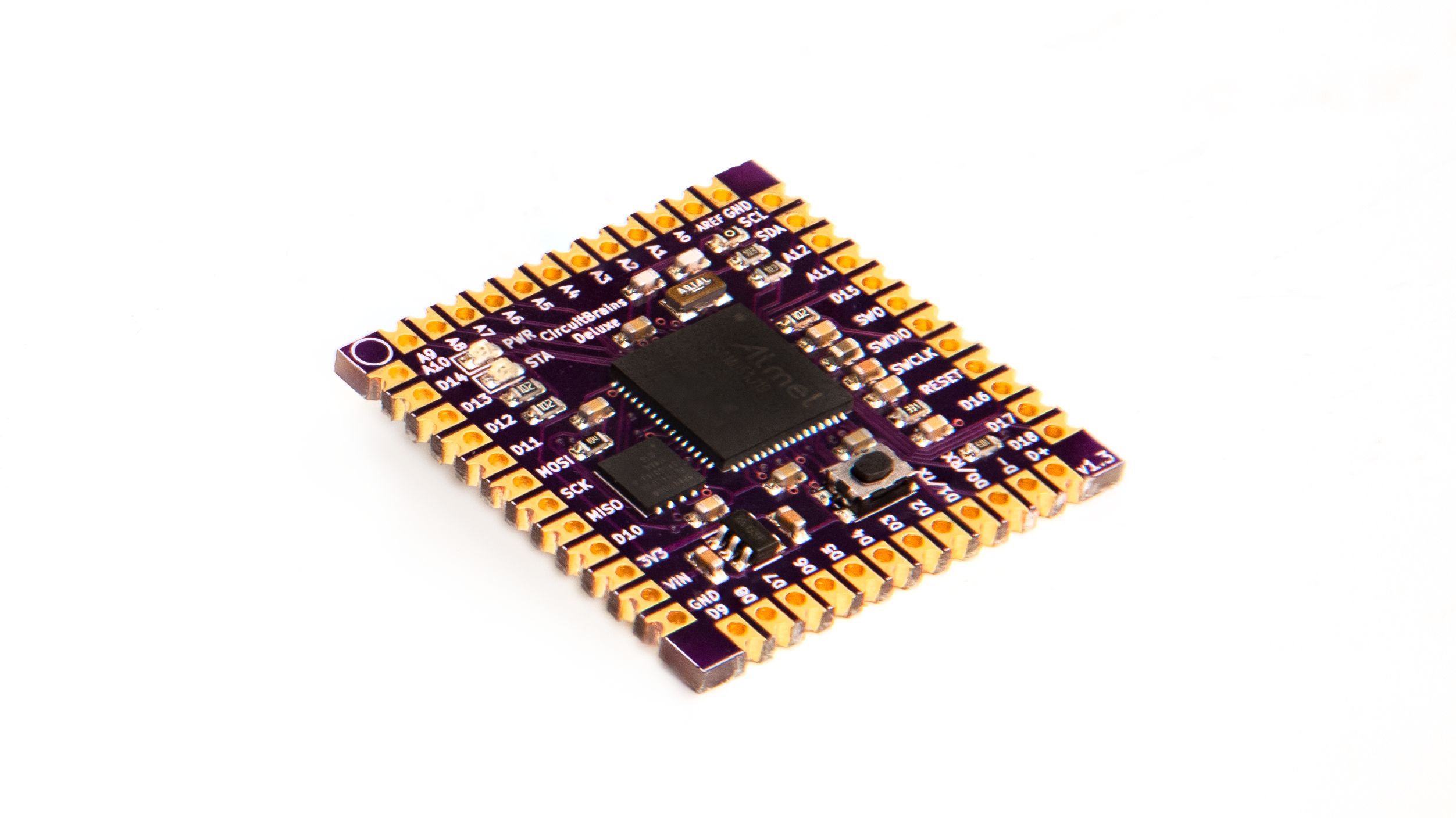
You may have noticed that CircuitBrains does not come with a built-in USB port. After careful consideration, the USB port was left out because it was too limiting on consumer project designs. Most USB ports require being placed on the perimeter of a project. This means that CircuitBrains with a USB port would require being placed at a project edge. It would also limit consumer designs to have a flat edge to accommodate the square shape of CircuitBrains. Want to use it on a circular PCB? That wouldn’t be very feasible with an included USB port. Further, it would have added 1.25 to 1.5x to the size of CircuitBrains to include the port and to re-work all the I/O pins around it.
The good news in all of this is that you get increased project flexibility, minimal footprint size, and that including a USB port in your design isn’t too difficult. The hardest part is probably choosing a part. Once you’ve chosen your part for your design, connect the pins to CircuitBrains as follows:
- 5V or VBUS to VIN
- GND to GND
- D+ to D+
- D- to D-
Be sure to route a differential pair for D- and D+ when routing your traces on your board. In KiCad, from the Route menu, choose Route Differential Pair and click on either D+ or D- and route from there. Here’s a video for doing this from Contextual Electronics. In Eagle / Fusion 360, it’s slightly more involved. However, there are good instructions here.
You could also include a temporary USB port in your design if you like. Lower-speed USB is pretty forgiving as long as you have the D- and D+ signal wires close to the same length, you can temporarily attach your CircuitBrains to a USB connect breakout board on a breadboard. Hook it up using lead wires, transfer your files, then disconnect it.
Import library and footprint into your EDA tool
In order to use the CircuitBrains library and footprint in either Kicad or Eagle, you will need to import the files. See instructions here for Kicad. See instructions here for Eagle.
Design a project around CircuitBrains
This step is pretty self explanatory. Use your imagination and come up with a great microcontroller project to use CircuitBrains in!
Fabricate your design
If you are fabricating a PCB to attach CircuitBrains to, there are several fab houses that will do this for you. For high quality prototypes, OSH Park is a solid choice. If you are doing a larger run, you may want to consider JLCPCB in China.
Solder CircuitBrains into/onto your project
After you’ve got all your components ready, assembly is the final hardware step. If you are doing a PCB project, solder CircuitBrains to your PCB. If you are doing a wearable project, use conductive thread or soft flexible silicon wires.
Write some code
CircuitPython is a great language for quickly bringing up a project. Adafruit has some great tutorials for getting started.