Project update 7 of 15
Flex PCB’s, Sensor Boards, Lower Low Power, and the Solar System on Your Wrist
by Joey CastilloOver the last few weeks I’ve been iterating on the final design for the temperature sensor board that’s going to come with Sensor Watch. As mentioned a couple of weeks ago, Sensor Watch has a 9-pin flex connector that lets you add additional hardware-level functionality to your Sensor Watch. I’ve played with probably a dozen different sensors for the watch so far, sensing everything from temperature and humidity to light and motion. But for this first iteration of the watch, I thought the humble temperature sensor would be a great start.
At last I think I have a design I’m happy with, and so this week I gave my PCB fabricator, PCBWay, approval for the first test panel of temperature boards! And that means I have a very cool panel rendering to show you:
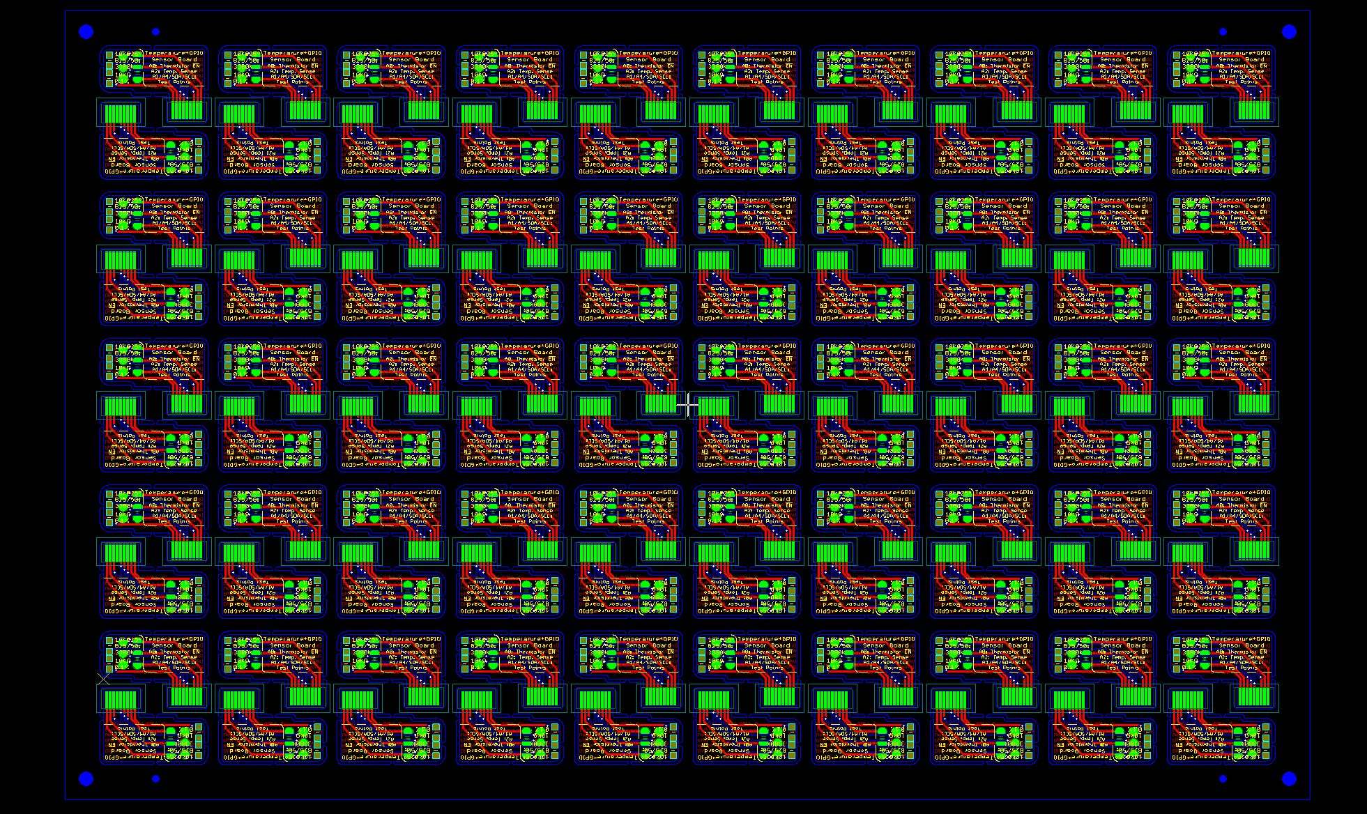
Full disclosure: PCBWay gave me a sponsorship discount for this panel, but they didn’t tell me anything in particular to say; I’m just sharing this rendering because I’m stoked! This is the first time I’ve panelized a flex board, and it’s fascinating to see how the panel comes together. In this case it’s 10 boards across by 10 down, which means that once I assemble these — I’m going to assemble them myself, right here in Brooklyn — I’ll have 100 sensor boards ready to go.
Unlike fiberglass PCB’s, there are no mouse bites to sand off; the boards are just a fraction of a millimeter thin, so I sense I can depanel them with scissors. Also unlike most fiberglass PCB’s, these flex PCBs also have a stiffener layer added near the gold-plated 9-pin contacts (it’s the teal outline around the nine bright green pads). I also just think it’s cool how they interlock right side up and upside down, like little tetrominos in a Tetris game.
I had two of these test panels made, and if all goes well, they’ll become the first 90 sensor boards that go out to the Special Edition backers. As I write this, the panels are in fabrication; I’m just so excited to get these in hand, and even more stoked to get them assembled and packaged up with those first 90 boards.
Getting a sense for sensor boards
I mentioned above that I’ve played with a ton of sensor board designs. Today I figured we could talk about the temperature sensor board and see all the stuff that we’ve stuffed into that one. Then I thought we could look at a few other boards that may inspire thoughts about the things you might like your watch to sense.
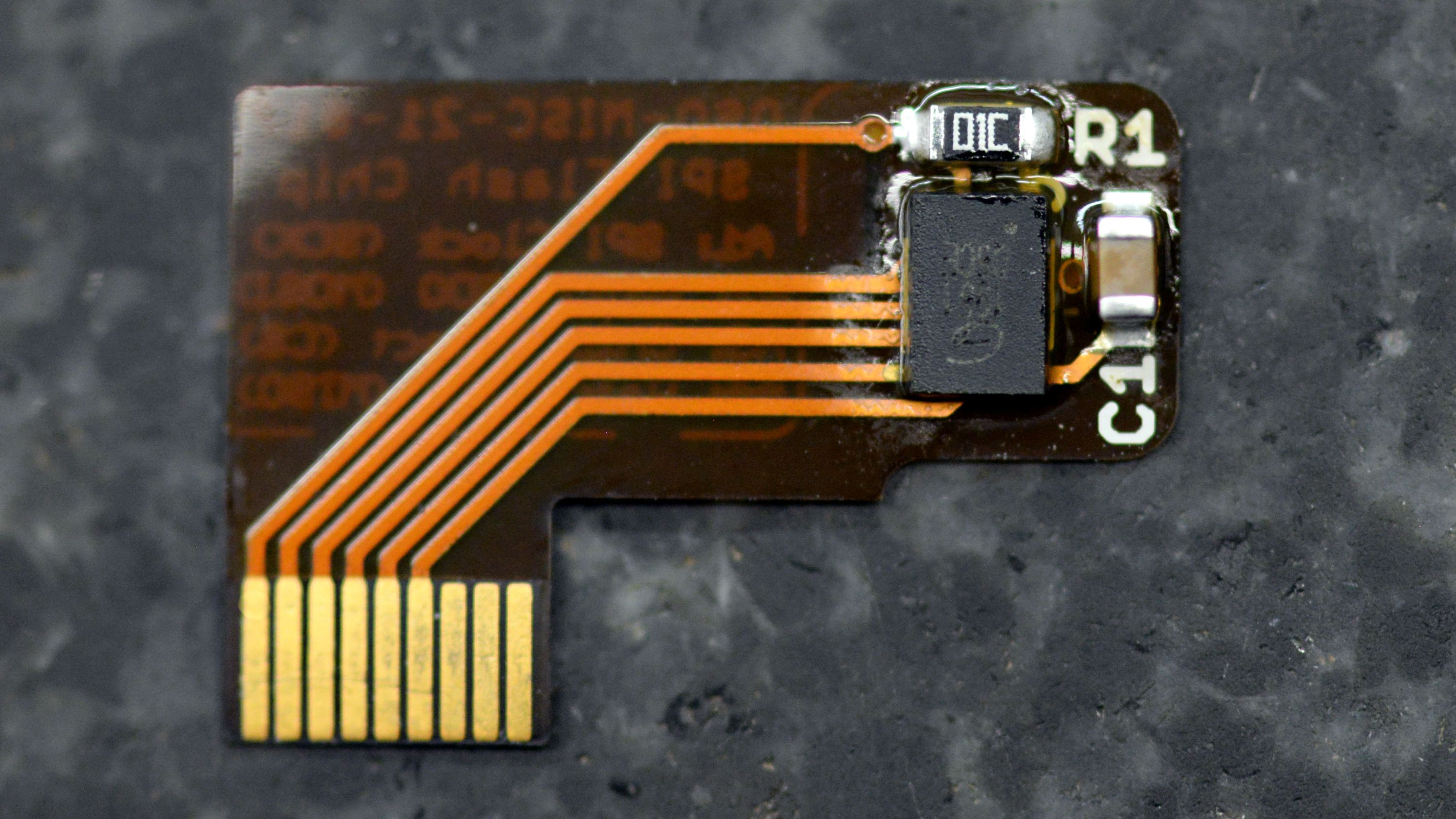
First, let’s take a look at the front side of the temperature sensor:
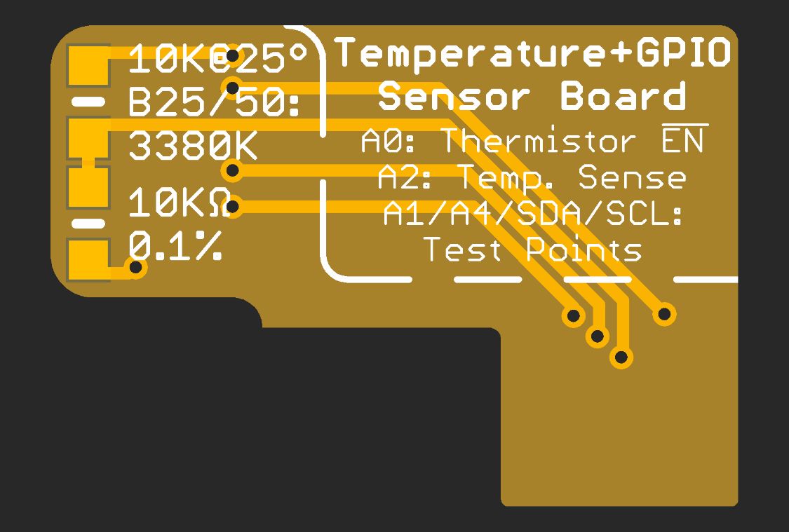
I’m a huge fan of self-documenting PCBs. There are only two parts on the front of this board, but thanks to the silkscreen documentation, it’s easy to see what they are: up top, there’s a 10KΩ thermistor with a B coefficient of 3380K, and below it is an extremely precise 10KΩ resistor with a tolerance of 0.1%. You don’t really have to worry about these values; Movement, the community firmware for Sensor Watch, has its temperature watch face already configured to read temperature values from this board. But in case you’re curious: these two components are arranged as a voltage divider: when the temperature goes up, the resistance of the thermistor goes down, and we can measure that change using the analog-to-digital converter in the SAM L22. With a little bit of math (and that B coefficient), we can turn that analog voltage level into a very precise temperature reading.
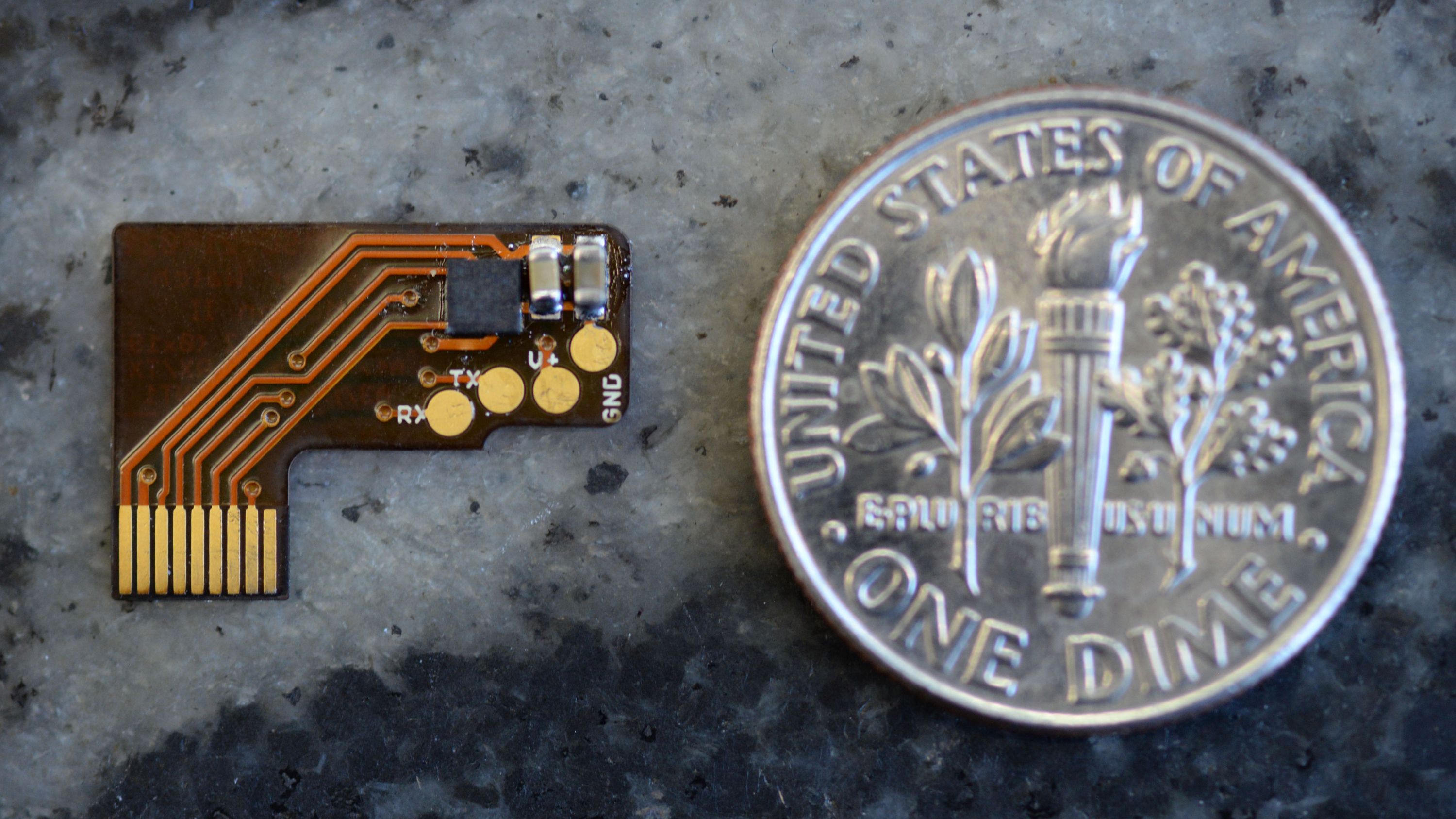
That’s the top side. Now let’s look at the bottom side.
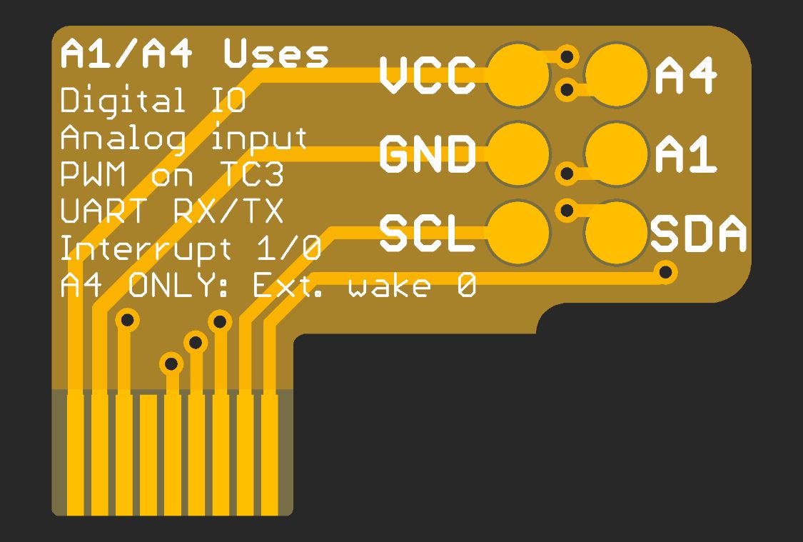
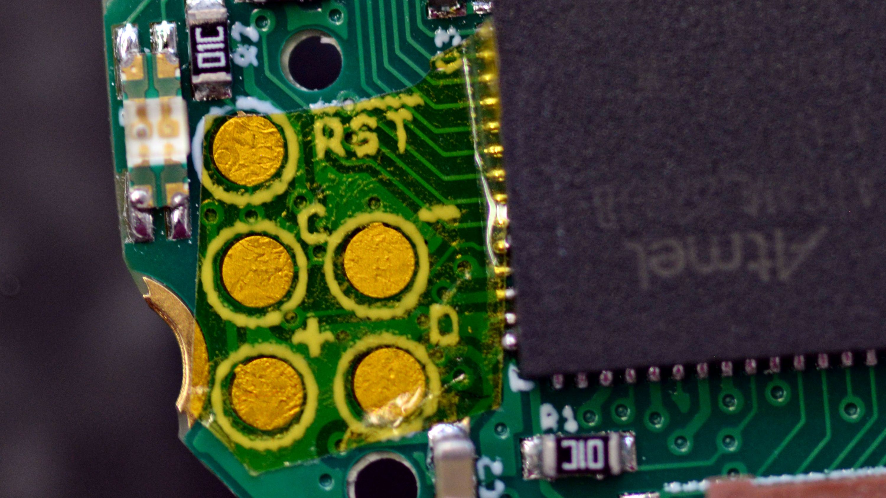
I’ll admit: this is probably for more advanced users. The thing is, the temperature sensor board only uses two of the seven signals on the 9-pin connector. These test points break out the I²C bus and two more GPIO pins, as well as pads for 3V power and ground. You can solder extremely fine enamel wires to these test points to test out other gadgets, or try to fit them in the watch case! There’s not a lot of room, but you could always 3D print a new backplate for the watch that gives you some extra space. (Note that if you solder to these test points, you should also put some tape on the debug pads next to the microcontroller, to keep your wires from hitting or shorting them.)
One thing to keep in mind as you read this is that the sensor board in Sensor Watch can be easily swapped; just because you got the temperature sensor board, that doesn’t mean you’re stuck with it. If a new sensor board comes around later and you decide you want that one, you can easily swap it out — no soldering required! So while temperature and test points are cool, one of the designs I played with (that sadly didn’t make the cut for the campaign) did away with those test points to offer a light sensor instead:
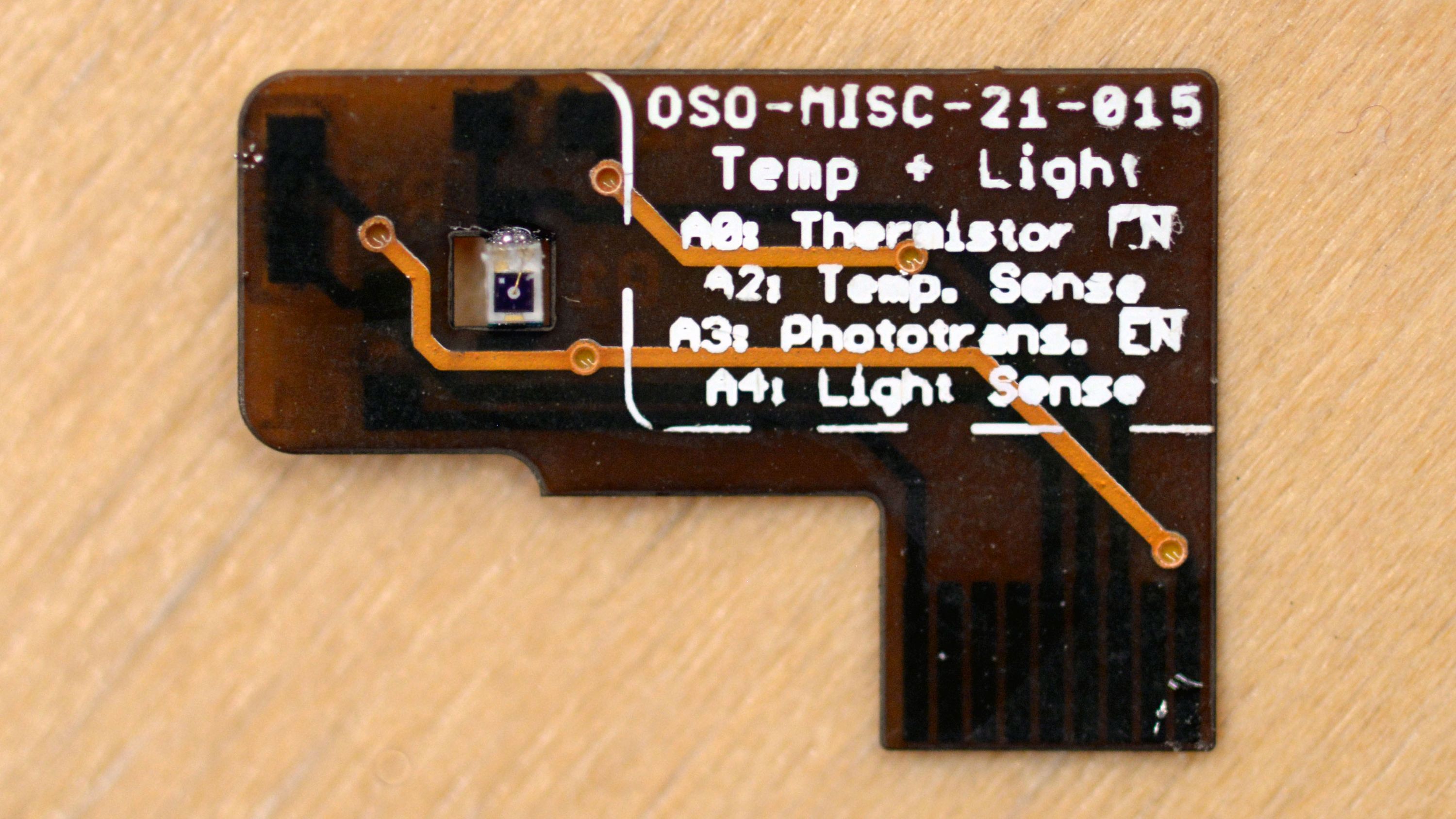
I decided not to do this one for the campaign because it required twice the number of parts, and the upside down phototransistor would have been a pain to place 100 at a time. Still, the design is open source hardware, so if you wanted to build one of these, you could do it yourself! Flex PCB’s in the Sensor Board form factor run $2.30 for three from OSH Park, and the parts are available from Mouser; all told, you could probably build three of these for $10. And before you ask: yes, enough light gets through the screen for this to be useful! The F-91W has a transflective LCD to let the LED backlight shine through to the front; it isn’t that surprising that some light shines through the other way.
One board that I desperately want to get made is an accelerometer board. This LIS2DW-based motion sensor consumes on the order of a few microamperes, and can sense motion at rates that could make it useful for things like step counting, sleep tracking and low power wake. It also opens the door to doing on-device machine learning: the Cortex M0+ in the watch is powerful enough to run machine learning models on this accelerometer data! Finally, the accelerometer can also detect single and double taps and signal them on an interrupt pin, effectively giving you two more buttons for interacting with the watch.
This board imagined incorporating a Flash chip for storing up to two megabytes of data. You might wonder: what on earth could I need two megabytes of data for on a watch? I ask: could you fit the whole timetable for New York City’s subway system on that chip? If so you could have the watch display scheduled departures at a few choice stations. Or maybe harmonic constituents for every tide station in the United States? That way you’re ready for tidepooling anywhere from San Diego to Shi Shi. Today I’m assembling a new board that combines a Flash chip and an accelerometer, to capture tons of accelerometer data for training a machine learning model.
Finally, here’s one that we’re still brainstorming over in the Sensor Watch forum: NFC. I don’t know if this is possible, but we’re considering whether the available surface area inside Sensor Watch is big enough for an NFC antenna. This could allow Sensor Watch to exchange bits of data with a smartphone via an NFC EEPROM on the I²C bus. Have expertise in NFC antenna design? Chime in over there if you like! I know folks are stoked for this feature and I would love to get a sense for whether it’s possible.
News of the Watch
Shortly after last week’s backer update went out, I started thinking: our power numbers are good, but what’s keeping them from being even better? Over the course of last Thursday and Friday, I found some significant power savings: 18 µA in wake mode, and about 4 µA in sleep. The impact is massive: Now I’m estimating that the watch has year-long battery life even without sleep mode — and with sleep mode, that could stretch even further!
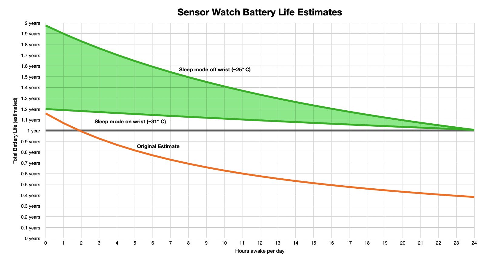
I also got a better sense of sleep mode power consumption when on-wrist versus off, which means I can estimate battery life in a range: depending on your wearing habits, the scenario I proposed in the last update — 2 hours awake per day — should now yield between 430 and 667 days of battery life on a single coin cell. If you want a technical deep dive into where we found those last few microamperes, I shared a thread with progress as I was doing the work. TL;DR: now we clock the buttons with a more efficient clock, and we spend less time checking the LCD voltage.
I’ve also been working on some new features: I ported over a moon phase app from my friends at Tidbyt, and that got me back to thinking about my white whale of a watch face: the orrery. An orrery is a device that displays the locations of the planets as they orbit the sun. Traditionally they’re fascinatingly complex devices full of gears and armatures, but the math is known and can be done on a computer (even a tiny one). Anyway I loved the idea of building that functionality into Sensor Watch, and now we have that. This effort also led to something even better: an astronomy complication.
The Astronomy watch face can calculate the positions of all the planets in the solar system, and display useful data points about them for the amateur astronomer: altitude and azimuth (which describe where you would look for them in the sky), right ascension and declination (which describe where they are relative to other stars), and distance in astronomical units (which isn’t technically that useful, but is very cool)! It still needs a bit of work before I can merge it into Movement, but I’m very excited that soon you’ll be able to wear the entire solar system on your wrist.
The campaign will wrap up on Tuesday — just five days from now! — and y’all, Sensor Watch is nearly 350% funded! I am sincerely blown away by the level of interest in this thing, and I cannot wait to start ordering parts and getting things in order for the final manufacturing run. Once again, I cannot thank you enough for your support! There won’t be regularly scheduled updates from here on out, but I’ll definitely be reaching out from time to time, whenever there’s progress to share or rad things are afoot.
- Joey