The PX-HER0 is an STM32-based board (STM32L072RB) designed for learning embedded development. The designer has done some amazing work on documenting the board and how to get started with embedded development with it in C, so I thought it would be a great place to start with getting Rust running on an embedded system. I decided to go with the PX-HER0 over others because it includes a screen, a number of hardware buttons, a micro-SD card reader, a whole bunch of GPIO, and other hardware that would allow me to experiment with a wide range of features without needing to switch hardware. I thought this would be a good place to start making the new OS I want to write, which I eventually want to port to a number of other platforms for educational purposes.
The “Hello World” of embedded software seems to be the “blinky LED,” so naturally I decided to start there. The PX-HER0 has an LED between buttons two and three called the “User LED,” meaning it’s something we can control and it’s not hooked into other hardware. So I decided to use it for this project.
In addition to the PX-HER0, the only other hardware I needed was my PC, an ordinary laptop running Linux (Ubuntu), and a hardware debugger. The PX-HER0 can be ordered on Crowd Supply with an STLINK-V3MINI debugger, which I bought, but I was a bit disappointed with it because, while it’s supported by OpenOCD, I had some trouble getting it to work with the version I had installed. It also seems to be focused more around ST’s products specifically and not just hardware debugging generally.
After looking at other alternatives I ended up getting a Segger J-Link EDU Mini. It’s a low-cost option targeted to education and hobbyists which supports a huge number of CPUs and devices.
I started with the QEMU and Hardware sections of The Embedded Rust Book so I could get a project setup I knew would build correctly. The biggest thing I want to mention, though, is that unlike the book, which targets the ARM Cortex-M3, we’re going to be targeting the ARM Cortex-M0+ the PX-HER0 uses. This means instead of using the thumbv7m-none-eabi, we’re going to use the thumbv6m-none-eabi. We’ll also be using a different memory layout in the memory.x file so it matches the layout of the PX-HER0.
There are a number of articles available that go over the basics of how to blink an LED in Rust, I used Hello, Rust: Blinking LEDs in a New Language to get things up and running. I detail all of the code components step-by-step and provide more resources in these blog posts:
However, what good is a bunch of code if it doesn’t actually run anywhere?! Next, I had to actually run the code on the PX-HER0 itself. First, I did it directly in the GNU Project Debugger (GDB) using the J-Link GDB server. The first blog post has all the details of the config I’m using in VS Code’s launch.json that allowed me to step through the code in VS Code.
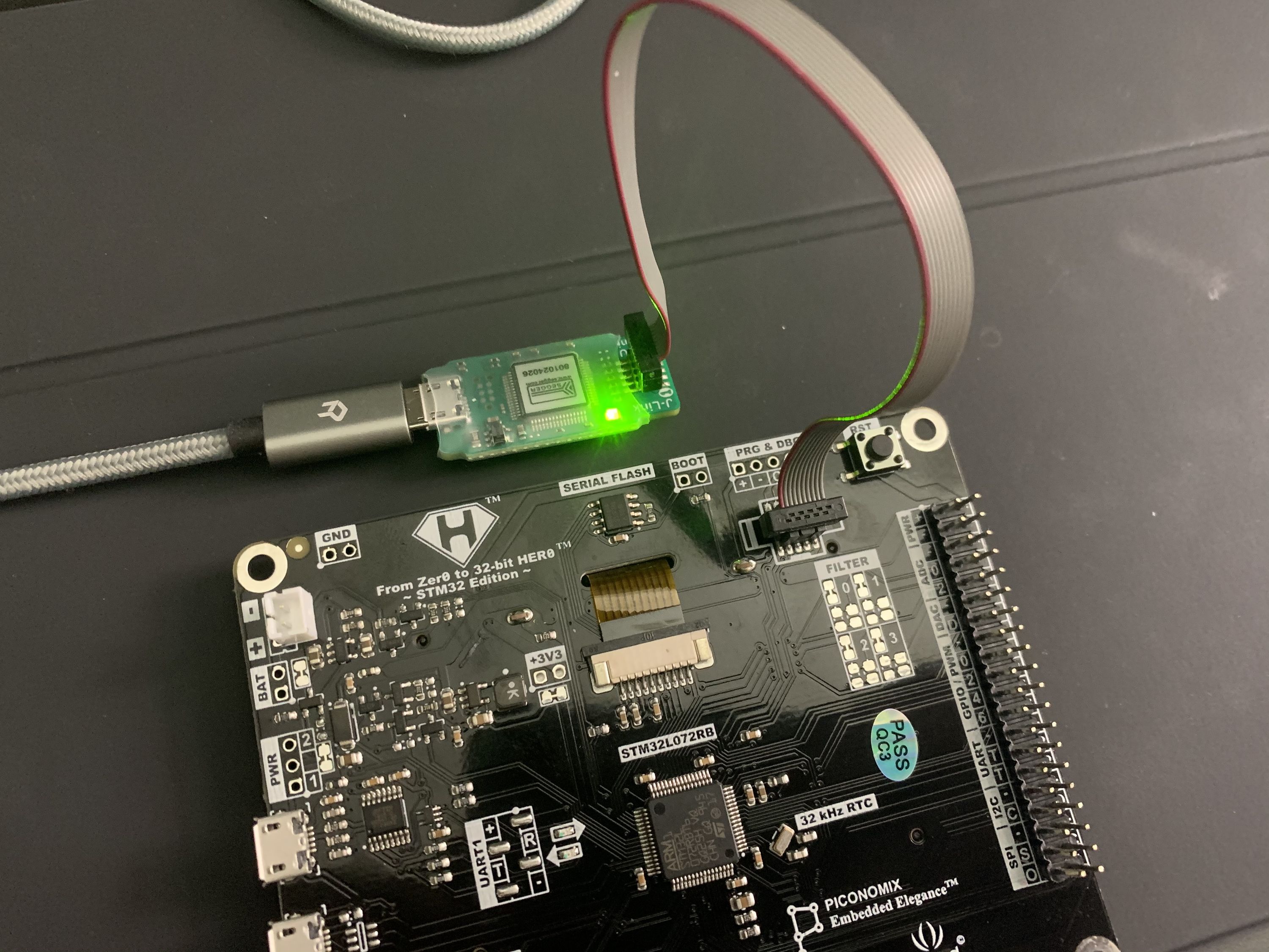
The picture above shows how I connected the J-Link EDU Mini to my PX-HER0 for these steps. My second micro-usb cable will be plugged into the PX-HER0’s USB1 port to provide power. You may need to set up some udev rules to allow yourself access to the debugger as a normal user. Again, all the code I used is detailed in the [first blog post] (https://me.kxd.dev/2020/10/04/rust-on-px-her0-part-1/)
The next steps I needed to code were:
- Creating an “LED” abstraction so we have an easy-to-use wrapper when working with LEDs. Instead of doing the high/low we could then just do an on/off.
- Read in a button press and turn the LED on when the button is pressed. This too will be easier if written into an abstraction.
This was pretty straightforward, although the "LED" abstraction was somewhat challenging. All the code details are in the second blog post (https://me.kxd.dev/2020/10/04/rust-on-px-her0-part-2/).
All in all, this was a very educational project with lots more potential for me to explore.