Project update 2 of 20
Define the Monitor Image Window to Show on Your Video LED Display
by Gordan GThe Pixblasters Video LED Controller has been designed to support professional-looking and easy to use video LED displays. To display any graphics and video with no limitations, Pixblasters users just need to plug in the monitor cable. Stills and animations, AVI, FLV, WMV, MP4, etc. - what you see on the computer monitor connected to the selected computer is what you get on the Pixblasters MS1 controller-driven LED display with absolutely no coding required!
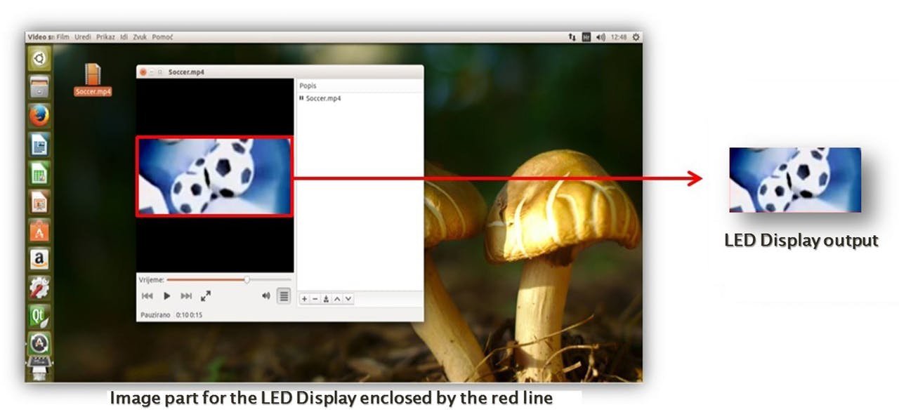
A single Pixblasters Video LED Controller supports up to 16,384 LEDs that can be arranged in LED display matrices with various resolutions. Although respectable, such LED driving capacity allows for the LED display of a smaller portion of standard monitor image. The Pixblasters LED controller receives the video formatted for the monitor, crops the image part selected for the LED display (Figure 1), and drives the LED strips by properly formatted video data. The complexity of LED driving is hidden from the driving computer and the WS2812B LEDs can be refreshed at the maximum 60 Hz refresh rate!
To keep the promise of supporting professional and easy-to-use video LED displays, the Pixblasters LED integrates several important features. For example, it includes an actual EDID chip to smoothly connect to any operating system as a standard monitor. Most consumer monitors these days carry inside an EEPROM chip called the EDID. It contains monitor’s name and technical info about its capabilities. This information enable any standard video source, i.e. the PC computer, to properly detect the monitor and automatically format the video image suitable for the specific monitor.
The Pixblasters really shines in big video installations, which may be oversized and hardly portable. Such installations accept only minimal maintenance and must work automatically when powered. Consequently, the LED controller requires retentive memory to store important configuration data, such as the coordinates of the image window for cropping. It also needs a "house-keeping" device to take care on SRAM-based FPGA chip with no internal storage for its configuration data, PC connectivity, multi-controller display configurations, etc. All these functions are integrated in on-board Microchip PIC18F26J50 microcontroller that connects to the PC and runs a simple User’s Interface. Besides the display configuration, it also enables firmware updates with new features.
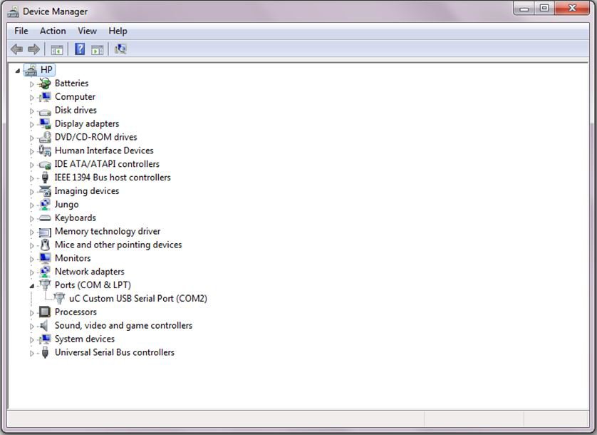
To program configuration data in the Pixblasters board, connect the board to the PC by USB cable. On PC machines with Microsoft Windows OS, a new COM port will be visible in the Device Manager (Figure 2). Open any terminal emulator application and establish the serial link with the following parameters: 115200 baud rate, 8 bit data, no parity, 1 bit stop bit and now flow controls.
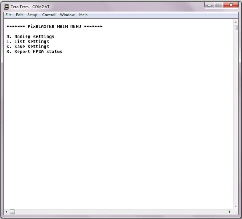
Hit the ENTER key and the Pixblasters User’s Interface will appear in the terminal emulator window (Figure 3).
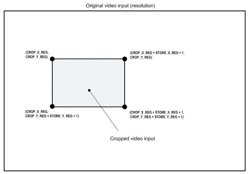
Select M. Modify Settings and setup the Cropping window position and sizing through the following registers: X_CROP, Y_CROP, X_STORE and Y_STORE. The Figure 4. explains how these registers define the video cropping window. Once programmed, the configuration data will be permanently stored in the PIC18F26J60 microcontroller’s internal flash memory, and at the next power up, the LED display will show the programmed image window.


