Project update 4 of 21
The Advantages of Galvanic Isolation
Hiya fellow engineers and makers!
Galvanic isolation is a very important property of a good UART adapter, though some people tend to dismiss it by claiming "I’m never working with high voltages, so I don’t need it". They couldn’t be more wrong. Let’s see what it is and why it is beneficial for everybody even if they don’t know it yet.
Uhm… galvanic what?
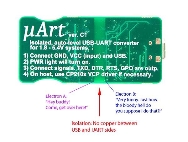
Galvanic isolation makes it possible to separate an electronic circuit into two circuits, where current cannot flow between the two parts but they can still exchange energy or information. The isolation acts like a barrier for electrons, and the only way for them to get around it is to apply extremely high voltages that are enough to break down this barrier (this is the primary reason why many think it is only good for isolating voltage levels, but as you’ll see shortly, it has a bunch of other usefull advantages too). This "breakdown voltage" is usually at least a couple of hundred volts high, often a lot higher. The goal of galvanic isolation is to prevent current flow between the two circuit parts completely, so it is sized/chosen to offer a higher breakdown voltage than what the application can ever see, even in the face of faults and errors.
Wait, if there are no connections over the barrier, how does information travel between the two sides? Well, using electrical means it doesn’t! This is solved using other methods, most commonly using light through components called optocouplers, but there are other solutions too.
Now that we’ve covered the basics and know what galvanic isolation actually is, let’s see why you’d want it.
Isolation from abnormal voltages
Let’s start with the most obvious reason that everbody tends to think about: isolation from high voltages. Because one side of the isolation does not "see" the voltage on the other side and current cannot flow between them, it means two circuits can safely exchange information over galvanic isolation even if they use incompatible - or outright dangerous - voltage levels. Let’s suppose that the IO (UART) side of the μArt somehow experiences a higher-than-normal voltage. Say your application circuit is powered from 12 V or maybe even 230 V mains. Of course, these voltages shouldn’t appear on the UART lines, but in case of faults this can still happen due to different reasons, such as component failure, a foreign metal body causing an unwanted short, user error, or simply just a design error. Without galvanic isolation, these voltages would most likely break down any component in the UART converter itself, making the high voltage appear on your USB bus, instantly and permanently damaging your computer, maybe even causing human injuries. Now, the μArt is only rated for 5.4 V working voltage at most, so in a case like this, your μArt will still be ruined. But importantly, the galvanic isolation makes sure that despite the damage caused to the μArt, the high voltage levels cannot cross the isolation barrier inside the UART adapter, protecting your $1000+ computer, preventing some cables from burning, and significantly lessening the threat to people.
It is important to note here that in contrast to common misbelief, you don’t need to work with high voltages like 230 V to benefit from this protection. At 230 V the effects are merely just more drastic and become dangerous to humans, but any voltage higher than 5 V (12 V is common enough) can damage your computer’s USB port, and galvanic isolation provides an effective and fool-proof protection. Futhermore, because no current can flow over the barrier, it also reliably protects your computer from other phenomena too, such as over-current, reverse current, shorts, or high transients.
Safe and worry-free hardware probing
Okay, so you’re one of those who claim you’ll never work with 5+ volts (like 12 V), and otherwise you will never make an error and your circuits will never fail. Fine, I’m quite sure this is a bold statement in many aspects, but I’ll play along. Galvanic isolation is still very handy for you.
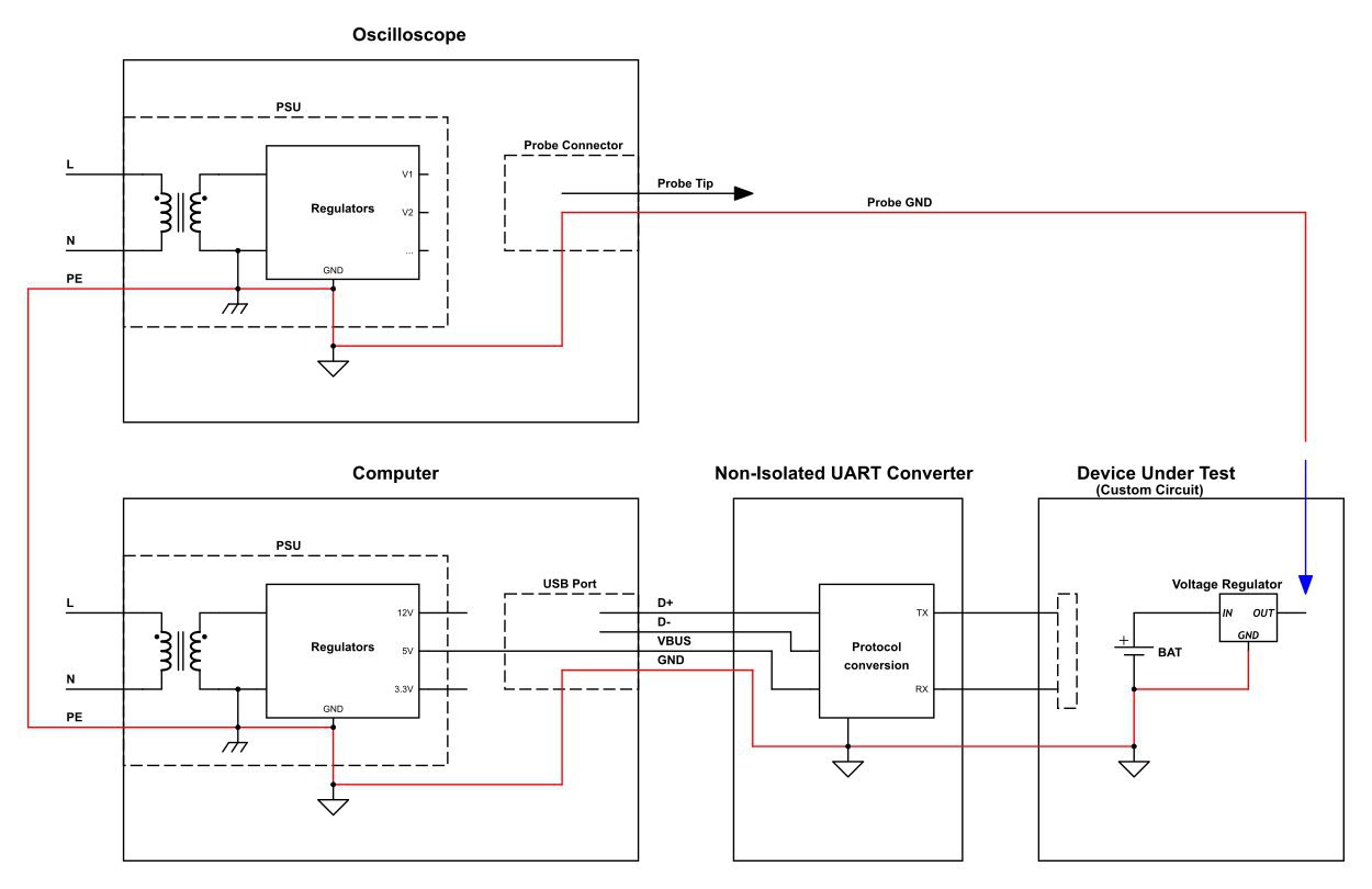
You see, without galvanic isolation, the ground (GND) of your circuit is electrically connected to the GND lead of the USB port through a low impedance path. What many people don’t realize, is that a computer’s USB port is often mains earth referenced, meaning the USB GND is actually connected to earth of your 230 V power grid. And yes, this is still true even though your computer has an isolated power supply. Now, don’t get scared, this is perfectly normal, safe, and is actually how it should be. But there are cases where it will bite you. Look at the following diagram.
What you see here is that a user is trying to probe his application circuit with his oscilloscope. His probe tip can be connected anywhere, or need not be connected at all. But note, the oscilloscope’s ground lead is usually also mains earth referenced, meaning your scope and your application are connected not only over the probe, but also through mains earth. Maybe you already see what this can lead to. If you connect the ground lead of your probe to, say, the power rail of your circuit, then you’ve just shorted out your power supply. At first this might seem impossible because you’ve seemingly only connected one wire (probe GND), so how can current flow without the circuit being closed? Well, the circuit is closed, over the common mains earth that both your oscilloscope and PC share. Want it or not, your probe GND is implicitly connected to GND of your own circuit.
This means attaching the probe ground anywhere other than circuit GND is prone to give you a power rail short, or at least a burned down digital output pin. Possible outcomes range from bad to tragic, from no damage but the circuit is magically not working when you probe it, to damaged components or even damage to the computer and/or to your expensive oscilloscope. You might ask, "but why would I connect my probe GND to anywhere other than circuit GND"? Well, you might not want it, but it can still happen and in practice does happen occasionally (slipped GND lead while attaching, probe clip jumping off, user remembering the false pin, human oversight, etc.).
Of course, all this is not a problem if you use a galvanically isolated adapter such as the μArt, because it severs the implicit connection between your application GND and equipment GND. The important takeaway here is, even with perfectly normal TTL/CMOS voltage levels of 5 V or less, using test and lab equipment is much safer and a lot less likely to cause damage with the μArt.
Noise-sensitive circuits
But wait, there’s more! As just discussed above, when using a non-isolated UART adapter, your own circuit’s GND will be connected to your computer’s USB GND, and in turn probably also to mains earth. Moreover, high-level (logic "1") output signals by the UART converter will be supplied by the computer’s USB supply rail. This means there are multiple ways for electrical noise generated by other USB devices, electrical noise generated inside your computer, and to some degree even noise generated by other appliances in your home / lab to conductively couple into your own circuit, both voltage rails and data lines. Note that this can happen even when your circuit is powered from its own independent and low-noise power-supply. While this is often not a problem, it sometimes is, for example when using high-precision analog-digital converters, strain gauge circuits, sensitive RF parts, and other precision analog stuff. In such cases, the noise conducted over the UART adapter can make your application give rubbish results or prevent its correct function altogether.
Galvanic isolation will greatly help with isolating conducted noise and ground loops, hence a galvanically isolated UART-adapter such as the μArt is more versatile, as it is more suitable for use with applications featuring sensitive and precision analog parts.
The μArt
As should be evident by now, galvanic isolation in the μArt plays a big role in making this UART adapter safer, easier to use, and more versatile. Furthermore, it is also what makes the voltage auto-sensing feature naturally available. Despite its usefulness though, galvanic isolation is often left out of UART adapters, partially because it is a significant cost factor (isolation components are not cheap), and sometimes because unexperienced engineers tend to think it limits communication speed as optocouplers are relatively slow. The μArt solves this problem by relying on magnetic coupling instead of optocouplers, which provides the same benefits without the limitations to speed. There is no real way around the increase in cost though, but the μArt was never meant to be the cheapest - it was meant to be the best and most reliable.


