Project update 9 of 21
UART Peer Circuits
Hiya fellow makers and engineers!
Whenever you use a USB to UART converter, you want to hook it up to some other circuit to communicate with. For many of you, this is going to be some pre-made off-the-shelf circuitry, like an evaluation board or a single-board computer. For many of you, however, it will be a custom contraption - a board of your own design. For all of you doing the latter, in this article we talk about what considerations and best practices there are when implementing your own UART interface.
The headers
At a minimum, your UART header should have four pins. TX, RX, GND and VIO. The first three should be obvious, but some of you tend to leave out VIO - it is the IO voltage supply. VIO allows you to use voltage-sensing and isolated adapters like the μArt. You may think there is no need to integrate this pin into the serial header as you can just use the traditional voltage headers at any time, but I would advise against that. First, adding it to the UART pins makes sure you always have the possibility for communication / debugging even when your VCC header would otherwise be occupied by some other peripheral. Second, and maybe much more importantly, it avoids mistakes and a lot of confusion. Your MCU or microprocessor might have multiple power supplies, your board as whole even more, and without an explicit VIO pin near your IOs, it may not be obvious which voltage header your serial converter needs to connect to. At worst, the wrong choice can lead to hardware damage due to overvoltage condition on your own circuit’s input pins. By adding a VIO pin to the UART header, you can clearly communicate to every user of your board (and to yourself as a reminder) to "Use this voltage level for UART".
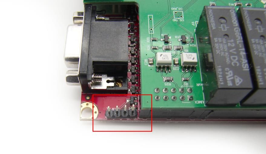
Should you use male or female headers? I recommend males on all open boards (circuits without a case) and for all boards (housed in or not) where the headers are internal. Cables tend to dangle and float around, so it is better if they get a female socket, because then even if they touch your board or electronics by accident, they won’t cause shorts. If you think it doesn’t matter because if the cables are male, the board’s connectors will be protected by being female, think twice. The board has a lot more open copper than just its pins and headers, and dangling wires are a threat to all of them. As a nice but very useful side-effect, this tip will also make it easier to probe your board. Below is an image of an Olimex base board implementing every aspect of what I am talking about (though I would have preferred if they placed the pin labels on the same side as the header).
The input circuitry
Ok, you have your UART pins ready for connection. Do you just lead them straight to your IC (microcontroller, microprocessor etc.) during layout? Of course you don’t. Though technically it works if you do, in that configuration, your IC is way too easily damaged, and you easily get undefined (noise, garbage) values on your floating inputs. Instead, I recommend you implement the following circuitry at a minimum. But for high-reliability or industrial devices, more sophisticated circuits can / should be used for even better protection and filtering.
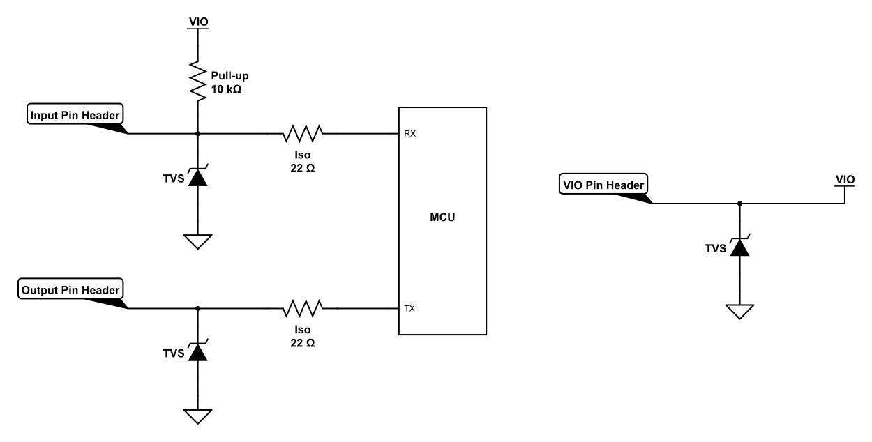
The above image illustrates multiple safety measures. First, the pull-up resistor avoids a floating input, which prevents random data to be "generated" when nothing is connected and during header (dis)connections. Notice two things here. If the pull-up is included - which is highly recommended, by the way - then it absolutely must be included in the receiving circuit. Way too often do I see pull-ups being connected to transmit pins. But they are useless there, because output pins cannot float, and they cannot prevent the receiving end from floating either when they are not connected to the peer device, which is exactly when inputs float. This also means though there is no pull-up necessary on IC pins which can only ever be outputs. Whenever I see a UART adapter implement a pull-up resistor on its TX pin, I have to question if its designer had sufficient understanding of the topic or if they were just putting it in by habit.
Then we have the ESD protection diode, this needs to be of a TVS (Transient Voltage Supressor) type. Just select one that has a working voltage right above your IO voltage and you should be fine. If you want to be thorough you can also make sure its Clamping Voltage is below the Absolute Maximum Rating of your IC pin, but in practice this is often unnecessary, as the IC will have its own basic ESD protection too, and yours only has the job of diverting most of the excess energy, not all of it.
And last but not least, we have our isolation resistor between the header and IC in series. This has not one, not two, but three different purposes - a true multi-talent! First of all, it greatly increases the effectiveness of your ESD diode, as its resistance, even at low values, will be a lot higher than the protection diode’s resistance while conducting - making sure current would rather flow over the diode than through your IC. It also limits edge-rate for output pins, band-limiting your signal and decreasing noise emissions from your circuitry. And lastly, given that you choose a sufficiently high value like 100 - 330 ohm (depending on IO voltage), it will serve as a current limiter to protect your pin from shorts and driver conflicts. You don’t need this last ‘feature’ if you’re using the μArt, as its pins are already current-limited (in which case just choose a generic value of 22 ohm), but you may also want to use other adapters too. Don’t include an isolation resistor on VIO though, as you cannot predict how much voltage dip the peer device can tolerate. Currents here can be 1000-100.000x larger than on data pins (a couple of tens of milliamps instead of micro- or nanoamps), so even a small resistance such as 2 ohm can create a dip of 0.1 V or larger.
Generic good layout practices apply. Place the TVS diode as close to the IO header as possible and as far away from your IC as you can. Also don’t include any vias or stubs between the header and the diode, but make sure the PCB trace goes straight through the TVS diode’s pad before reaching anything else. The isolation resistor should be closer to the ESD diode instead of your IC for best ESD protection.
Handshaking
Should you use handshaking? This depends on multiple factors, like the average data rate, buffer lengths in the communication peers, the consequences of losing some data bytes here and there, the processing speed of the devices involved, and more. If you are using very high baudrates and transferring a lot of binary data, you might want to consider it. But if all we are talking about is a console interface or debug output, then just forget about it completely. Should you decide to use handshaking though, just do yourself a favor and stick with hardware handshaking and add two more pins for CTS and RTS. Stay clear of Xon/Xoff (software handshaking).
First of all, you must escape (or encode) all your binary data when using Xon/Xoff, and transferring binary data is one of the probable reasons you have chosen handshaking in the first place. Second, it is just plainly unreliable in practice, even if it works most of the time. Different devices handle control bytes for handshaking differently. Some have bugs, others don’t support queue jumping, some depend on driver options, and you may be surprised how Xon/Xoff can fail you in slightly mysterious ways that are hard to debug. Factor in that many terminal programs default to software handshaking unless reconfigured. And at some points, software handshaking is almost broken by design. Take the example of two devices sending "stop" bytes at the same time, at which point no matter what common implementation your vendor has chosen, I can assure you none of them is correct, as you either have a deadlock or risk losing data. There is actually one valid way out, which is repeatedly sending "continue" bytes and letting them jump the transmit buffer, but to the best of my knowledge no UART bridge implements this, and even if one did it wouldn’t always work due to how some receiving devices handle a buffer overflow. Yep, if I think about it, I dare to say Xon/Xoff is broken by design. In contrast, handshaking using RTS/CTS, even if you do it in firmware, is more robust, there is little room for device incompatbilities, and is actually easy to implement correctly.
Labeling
The last topic we are going to talk about today is labeling your UART pins. I know of some devices (thankfully none of them are UART adapters) that label the UART input pin as TX (because it’s where you connect the TX pin of the peer) and the output pin as RX (where the external RX wire connects). Don’t do this! This is like labeling a battery wire VIN because it’s where the VIN pin of the device connects. Insane, right? All pins should be labeled from the perspective of the device that the pin is part of. Call your output TX (because an output transmits) and your input RX. This is the standard convention used basically everywhere, and everybody knows to connect one device’s RX to the other’s TX, and vice-versa, with UARTs. Labeling your pins differently will almost certainly result in hardware damage, as nobody bothers to check if RX is really the input and TX is really the output, and boom you have a destroyed pin. Except, of course, if you use a μArt, then nothing gets damaged :) But it still won’t work.
Conclusion
Implementing a UART interface in your own device is an easy task. Maybe too easy, which could be why sometimes it isn’t taken seriously. But by giving it just a little bit more thought, adhering to well-establish conventions, and using a few cheap passive components, you can make a UART header that will not only make your board last longer, but is easy to use and understand for every user of your circuit.