Project update 10 of 17
Iterative Hardware Improvements
by Patrick VThe Pareto principle, also known as the 80/20 rule, states that for many outcomes, roughly 80% of consequences come from 20% of causes. In product design, this often means that even if most of the product works as intended (the 80%), if the final details aren’t right (the 20%), your product will be horrible and users will likely hate it. The pursuit of getting the last 20% right is the reason that both ManT1S and ManT1S-Bridge are already on revision five before they are even released!
ManT1S Revisions
The picture below shows the five ManT1S hardware revisions up till now:
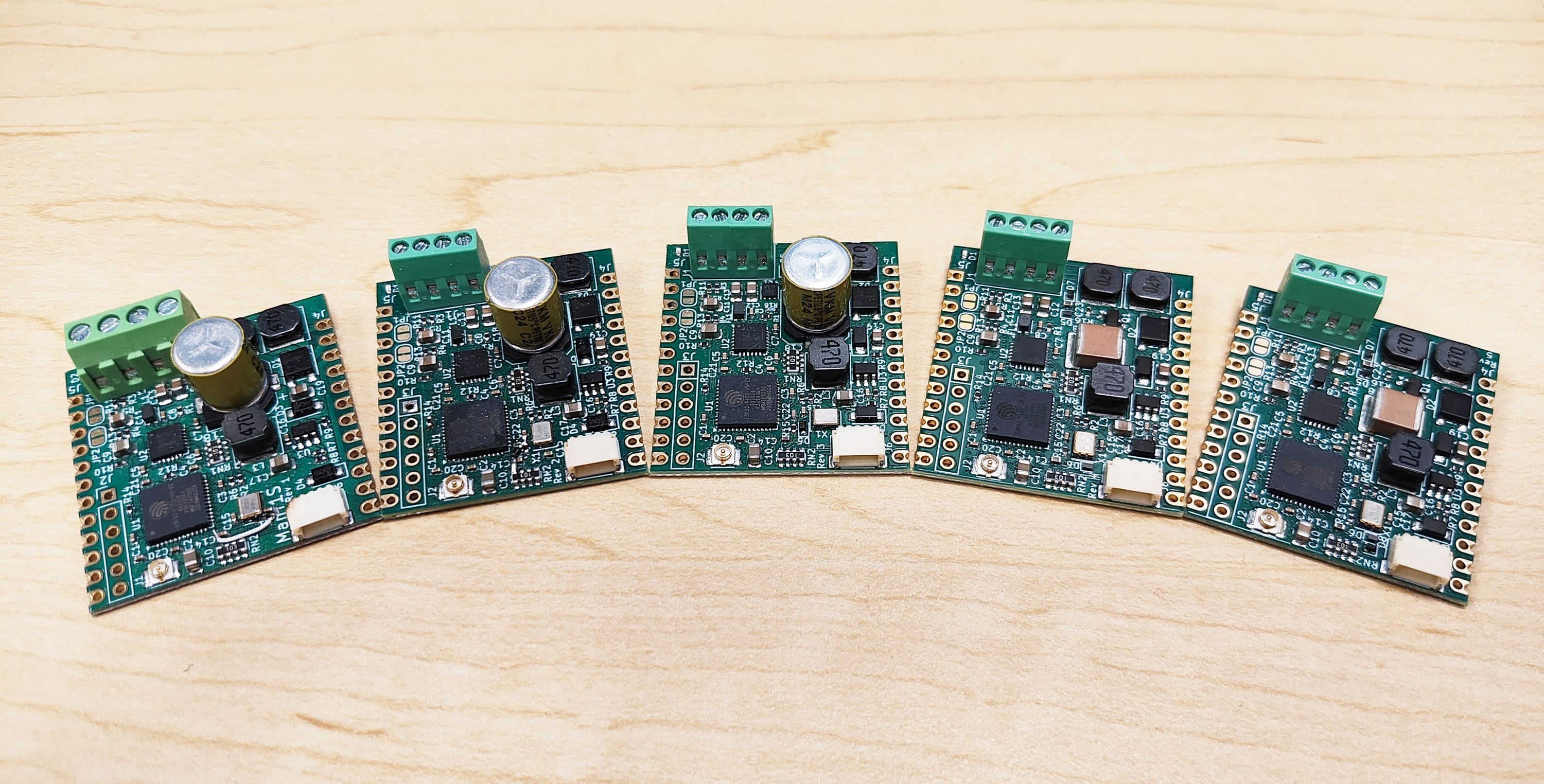
Starting on the left, revision one had quite a bit wrong with it. For one thing, you might notice that it’s wider than the others. From the start, I wanted the ManT1S to fit in solderless breadboards, but I screwed up my initial revision and it was 0.1" too wide to fit! That was something that obviously needed fixing. You can also see a little bodge wire and a few extra components by the 50 MHz crystal oscillator. You would think that after getting the IO0 pin’s PHY clock and programming combo to work reliably on the wESP32, this would be a solved problem, but it seems to behave different for every PHY. Without the added RC circuit, the crystal oscillator would start too quickly and the ESP32 would randomly boot into the flash application or bootloader mode.
Revision two scrunched the board to the correct width to fit on a solderless breadboard and added these new parts. At this point, it worked well enough to do more thorough testing with a combination of rev. 2 boards and some reworked rev. 1 boards. It became obvious that the RC circuit to delay the start of the crystal oscillator also needed to have a diode added to quickly discharge the capacitor when EN is pulled low, to make sure programming flash worked reliably. It also became obvious that the inrush current of many (up to eight) nodes on a mixing segment was too much for many power supplies to handle, so the supply powering the mixing segment would go into a hiccup mode. These early revisions had 100 uF electrolytic bulk caps and no soft-start circuitry and it had become clear I needed to add soft start circuitry if this was going to work.
Revision three was the first to have these changes, including soft-start using an NMOS to slowly connect the low side of the bulk cap to ground on powerup. While this sort of worked for the ManT1S by itself, any bulk capacitance added by the user to the high-voltage supply was not soft started. This was still a problem: I wanted soft-start to work for circuitry users connected to the ManT1S as well, so users wouldn’t have to worry about what capacitance they added. The soft-start should slowly connect the top of the bulk cap (plus any external loads) to V+, instead of the bottom of the cap to ground.
Revision four switched the soft-start system to a PMOS slowly connecting the bulk cap to V+ and applied soft-start to any user circuitry connected to the V+ pin as well. The bulk capacitance on the ManT1S was also reduced from 100 uF electrolytic to 10 uF ceramic. I decided to only include the capacitance needed by the ManT1S itself, externally connected power converters and other circuitry could add their own capacitance and would now be soft-started correctly.
Revision four was going to be the final revision at release, but revision five was done to add the CE/UKCA logos Mouser required, make a few cosmetic changes (PODL1/2 labels changed to POLD+/-), change the shape of the termination pads on the bottom of the board, and add one more diode to ensure the micro would boot cleanly even with short power-disconnect events.
ManT1S-Bridge Revisions
The ManT1S-Bridge also went through five revisions, here are the first three (where most of the action happened):
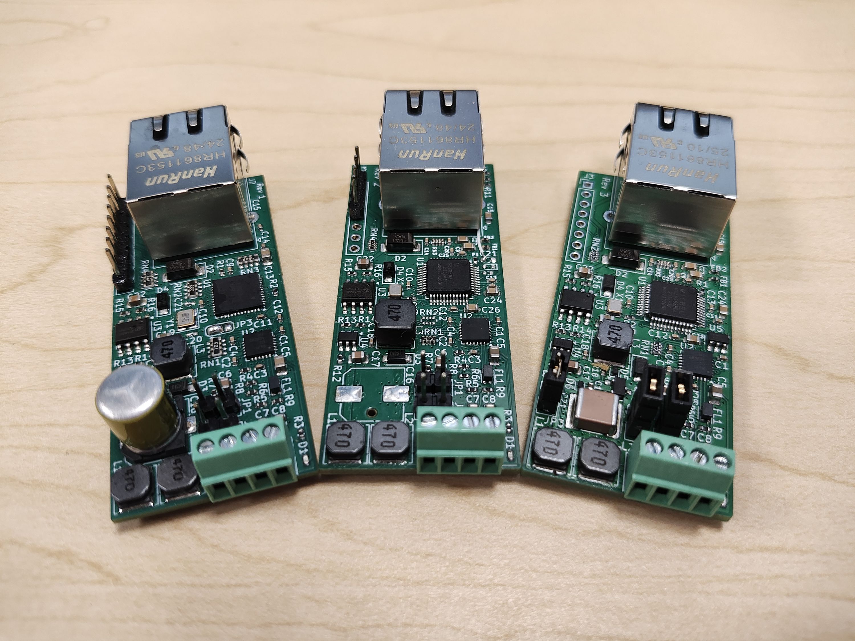
The first revision was a complete dud, I really did not know what I was doing. I had found information about Ethernet PHYs with master and slave modes for their RMII interfaces and I was under the (very mistaken) impression that I could have an Ethernet PHY connected to a T1S PHY using RMII in master/slave configuration. This did exactly nothing. :)
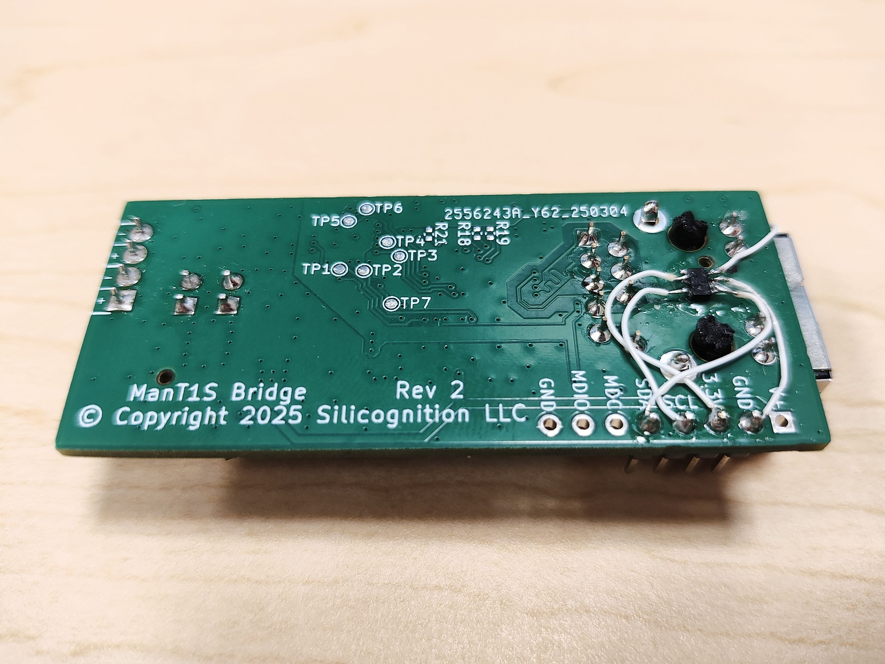
After doing more research, I figured out I needed to use a network switch chip. I ended up using the KSZ8863RLL, which has two Ethernet PHY interfaces and one Ethernet MAC interface which I could connect to the LAN8671 T1S PHY. This was still largely experimental because I had no idea if I would be able to get things configured correctly to do what I wanted. I was hoping configuration could be done solely with strap pins. This turned out not to be the case. When I received prototypes, they still did nothing. It took a deep dive into the datasheet and lots of experimentation with a I2CMini, but I finally figured out the needed configuration to enable bridging between Ethernet and T1S! However, to set up the correct configuration on every boot, it was necessary to add a microcontroller. I tested this with a dead-bug hack to revision two first:
Once that was confirmed to work, revision three implemented it properly in the board layout. At the same time, the changes to the soft-start circuitry and bulk capacitance that were figured out on the ManT1S were also added to the ManT1S-Bridge.
The remaining revisions were mostly about making the power options more flexible. Revision four added both PoE and T1S voltage to the auxiliary header, while revision five also made it possible to completely disconnect PoE ground from circuit ground for complete galvanic isolation. This isolation is possible when not using PoE, but also when using PoE by adding an external isolated DC/DC converter connected to the auxiliary header. This change was made based on feedback from a backer. Thank you! I love it when I can make my product better before release by knowing what will be useful to customers. :) This revision also fixed a problem when not using PoE that I had almost overlooked, because most of my testing had been done with PoE.
It should be noted that, to make it possible to add an isolated DC/DC converter, the pinout of the auxiliary header had to be changed from what has been shown in the campaign pictures and video. The new pinout for revision 5 is shown in this rendering:
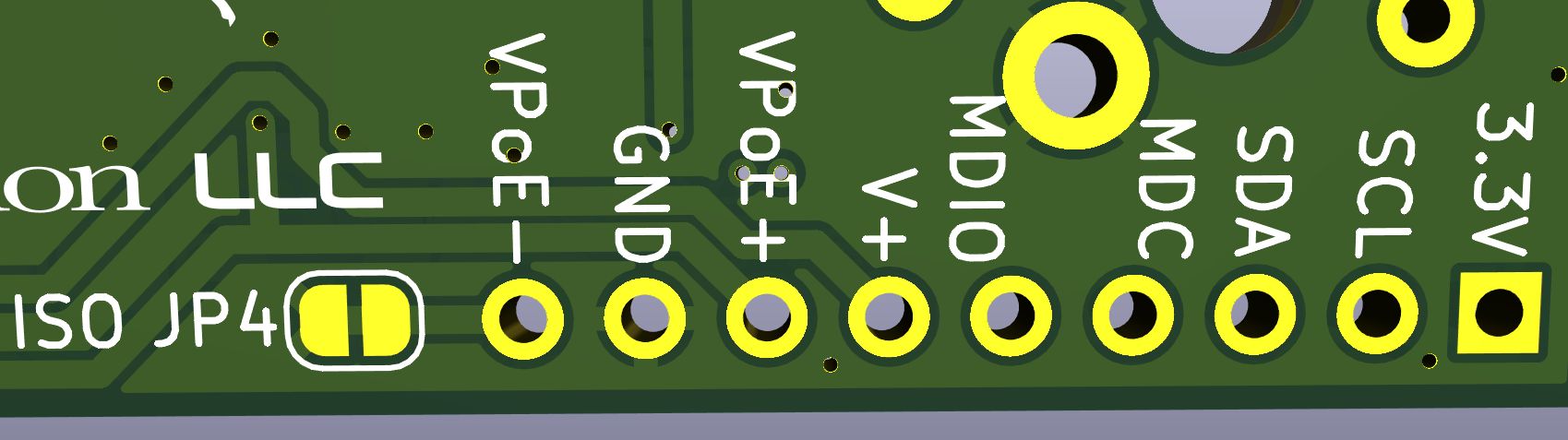
Solder jumper JP4 can be cut to provide galvanic isolation between the PoE and T1S sides by disconnecting the grounds. By providing VPoE+ and VPoE- on the PoE side, and GND and V+ on the T1S side, all connections needed to provide isolated power conversion are present on the auxiliary header.
We’re in the Home Stretch!
As you can see from the above, much work has gone into making sure that networking and power distribution both work seamlessly, so that you, the user, don’t have to worry about them. The details I found most important to get right were seamless bridging to Ethernet and seamless power delivery by solving the inrush current problem using soft start circuitry. By having these in place on every module, you won’t have to worry about technical details and instead you can focus on your application.
The campaign is nearly over, we are over 500% funded, and I would like to thank you all very much for your support! It’s been a long ride, but we’re almost at the finish line. :) Please continue to share my project in your social networks so we can make a strong finish!