Project update 14 of 17
Power Considerations, Part Two - Connections
by Patrick VTime for part two on power: What power connections does each board in the ManT1S ecosystem have, and how do you use them?
But first, a quick update on manufacturing:
The ManT1S production PCBs are currently being manufactured, and the production assembly order has been placed with my contract manufacturer, KingTop Technology. In the meantime, I’m still trying to work through the PMS150C-or-G question for the ManT1S-Bridge with Sino-Mos (who program them). Chinese New Year had interrupted this effort, but I’ll soon get started on getting it going again. It’s an annoying hangup that was a bit unexpected and it first came up because Sino-Mos told me PMS150C supply was tight in the market. We will see which way this goes, but if all else fails, I can always program and add this part myself (I have enough PMS150C in stock to cover the campaign). At this point, it’s mostly about figuring out the fastest way to get the ManT1S-Bridge produced.
Now back to the meat of this update: What’s up with the various power connections on these boards?
ManT1S Power Connections
On the back of the ManT1S, the pin labels highlight power connections with inverted color labels (dark text on a white background):
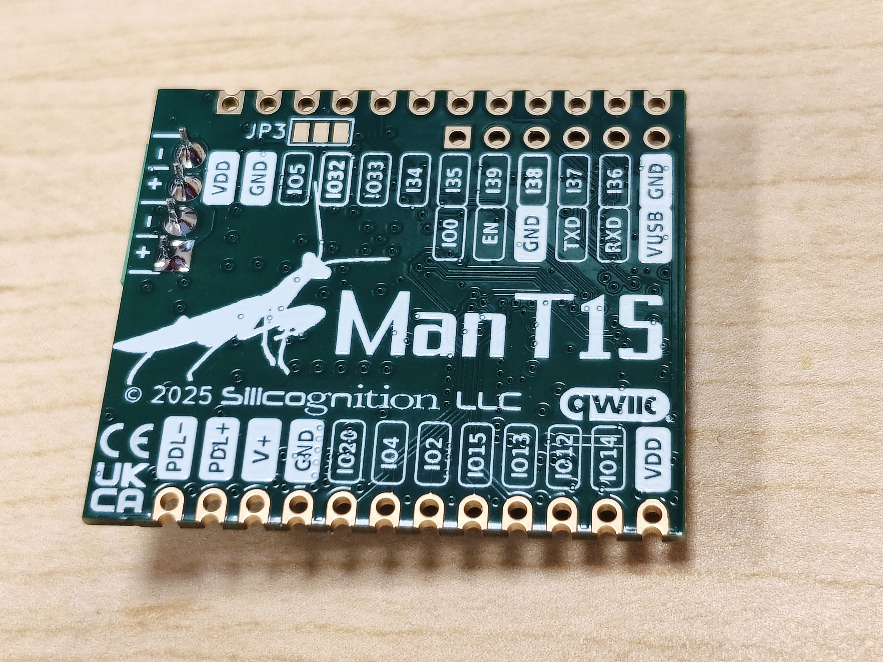
These are the available power connections and their use:
GND: Circuit ground. This is available on both castellated edges and on programming interface J3.PDL+andPDL-: Positive and negative terminal of Power over Data Line. These connections can be used to inject power into the mixing segment or (in rare cases) to extract power from the mixing segment. However, extracting power should normally be done fromV+, for reasons explained below. Unless you are injecting power, do not add bulk capacitance to these terminals, as they are not soft-started. As explained before, the polarity of these signals doesn't matter to the ManT1S, but please follow the +/- convention to maintain compatibility with the ManT1S-Bridge.V+: This is the main high-voltage power rail of the board, bridge rectified fromPDL+andPDL-so it's always positive versusGND. It can be used to extract the mixing segment Power over Data Line voltage to be used by your application. This is where you would connect your own voltage converters to generate voltages you may need for your application. If you use the ManT1S-Bridge to power your mixing segment, make sure that any circuitry connected here can handle the maximum PoE voltage of 57 V! Or, if you need maximum power and are using a higher voltage (up to 75 V), make sure the circuitry attached toV+on all your nodes can handle the voltage. The connection ofV+to the mixing segment is soft-started on power-up to avoid overloading of the power source that powers the mixing segment. Without soft-start, the sudden load of the bulk capacitance on all the nodes would easily overload the power supply, making it go into a hiccup mode. Soft-start in most cases alleviates this issue, but keep your load bulk capacitance in the system modest compared to the bulk capacitance of the power source. You can also inject power intoV+to power just the ManT1S itself, not the mixing segment. In this case, if there's any chance that the mixing segment would be powered with a voltage higher than your local powerV+source, you should inject yourV+power through a diode with high enough reverse voltage rating to protect your power source.VDD: This is the local 3.3 V power rail, generated fromV+. This is output-only, do not inject external 3.3 V! The maximum combined load on the 3.3 V rail is 1 A, so usually there's plenty of power left to power your additional 3.3 V circuitry from this rail.VUSB: USB voltage input from the wESP32-Prog or wESP32-Prog-C programmer that can be connected to J3. This is usually ~5 V (minus diode drop), but can be ~12 V when using a wESP32-Prog-C with theReq 12Vjumper bridged and connected to a suitable USB PD power supply. This voltage is connected toV+through a diode.
ManT1S-Bridge Power Connections
The pinout of ManT1S-Bridge auxiliary connector J3 has changed between various revisions, so please make sure to refer to the information here for the actual pinout on revision 5 that will be shipped to campaign backers:
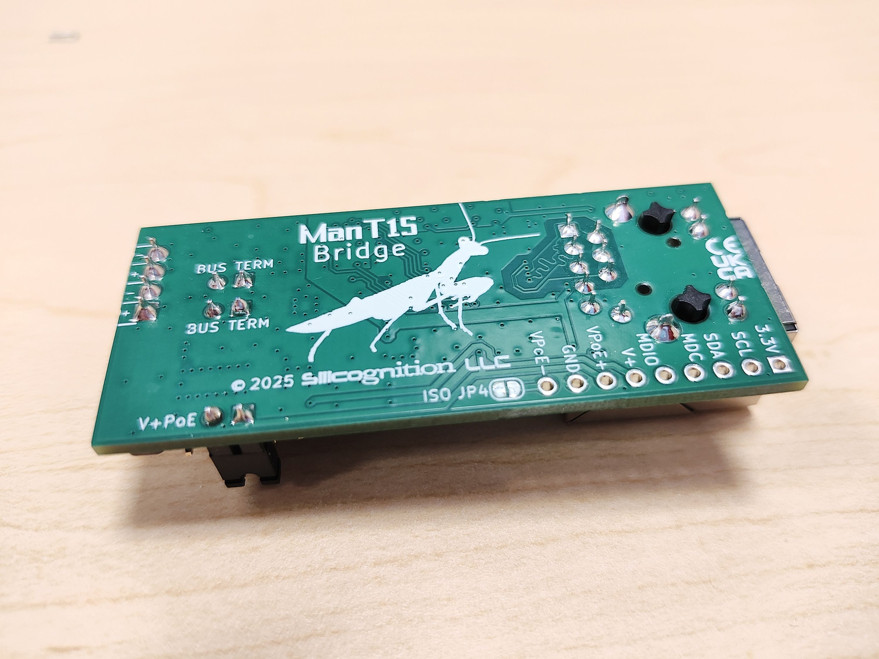
Ignoring the configuration interfaces for the T1S PHY (MDC and MDIO) and network switch chip (SDA and SDL), these are the available power connections and their use:
GND: Circuit ground. The ManT1S mixing segment is not isolated, so this is also the mixing segment DC ground reference. In addition, by default there is no ground and power isolation to the Ethernet cable, so this is also the PoE voltage reference, unless solder jumper JP4 (closed by default) is cut open. Opening JP4 allows for galvanic isolation from the Ethernet cable if not powering the mixing segment from PoE, or with the addition of isolated power conversion circuitry when PoE power is desired.V+: Mixing segment positive voltage. The mixing segment voltage can be either extracted from or injected into this pin. Because the ManT1S-Bridge by default is used to power the mixing segment, no diode bridge is included, so mind the mixing segment polarity if powered from another source.VPoE-: PoE power negative terminal, or ground reference. By default this is connected to GND through solder jumper JP4.VPoE+: PoE power positive terminal. If you want to power the mixing segment from non-isolated PoE power, connect the RJ45 to a PoE switch and bridge jumper JP3/V+PoE to connectVPoE+toV+through a diode. This is the default factory configuration. If you don't want PoE power on the mixing segment, remove the JP3/V+PoE jumper.3.3V: Local 3.3 V power rail, generated fromV+. This is output-only, do not inject external 3.3 V! The maximum combined load on the 3.3 V rail is 1 A, so usually there's plenty of power left to power additional 3.3 V circuitry from this rail.
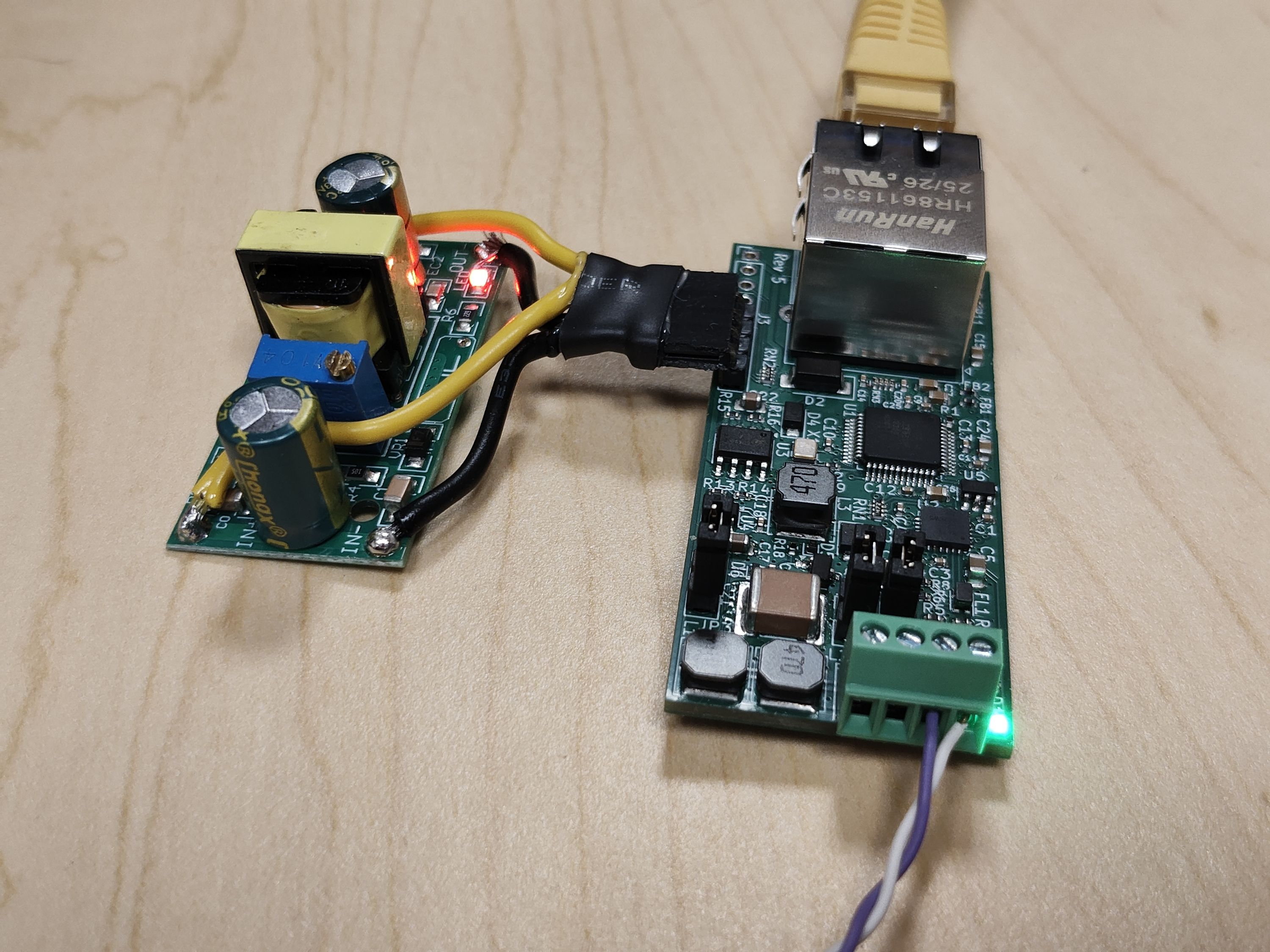
Normal, non-isolated PoE power to the mixing segment is available if JP3 and JP4 are both closed. Opening JP3 is a quick way to remove PoE power from the mixing segment, but the T1S mixing segment will not be galvanically isolated from the Ethernet cable. By opening both JP3 and JP4 you get galvanic isolation, and by connecting an isolated power converter between VPoE+/VPoE- and V+/GND, it is possible to achieve isolated power from PoE to the T1S mixing segment as shown here:
ManT1S-Gadget Power Connections
One of the use cases of the ManT1S-Gadget is to inject power into the mixing segment. The backside of the board shows these connections:
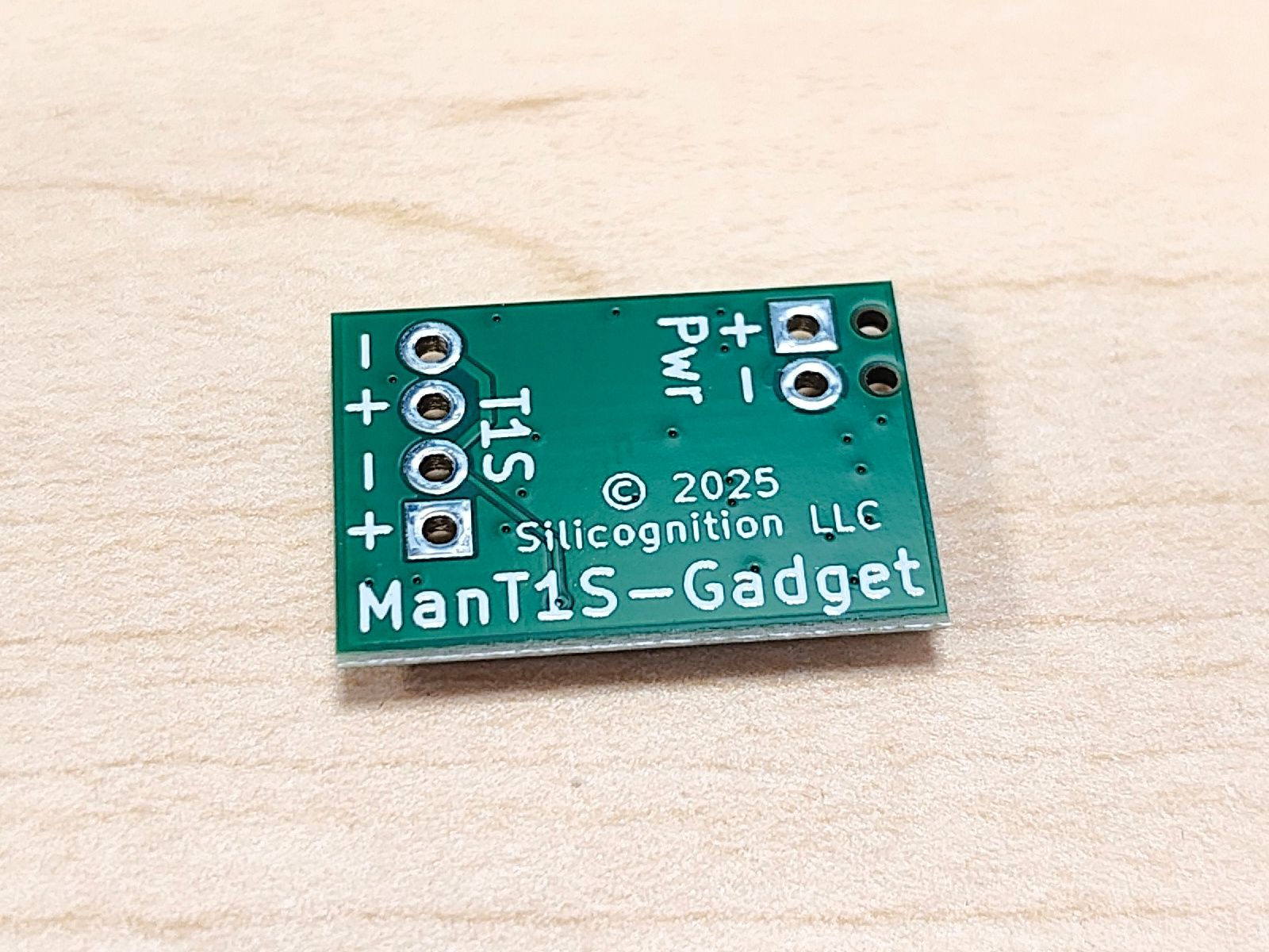
The Pwr+/Pwr- connector is where you can apply a power source to power the mixing segment. The circuitry is equivalent to the PDL+ and PDL- signals on the ManT1S. In principle, you can also extract power from the mixing segment at these terminals, but the same caveats apply as for the PDL+ and PDL- signals on the ManT1S: mind the polarity, and make sure there is no bulk capacitance connected unless you’re injecting power, or you add your own soft-start circuitry.
That’s it for the (fairly dry) subject of power connections, in a future third power update I will explain how you can use these power connections to practically power your ManT1S system!