Project update 13 of 17
Power Considerations, Part One - Voltage
by Patrick VI should have written the story of ManT1S’ power handling much earlier (I had intended to do it during the campaign!) but I never got around to it until now because I never found the time and it is such a large subject to cover! Why is it a large subject? Because the ManT1S provides you with considerable flexibility in how it is powered, so there are some fundamental principles that need to be explained and details to go over to give you as a user the best chance of a successful deployment.
For this reason, I decided to split everything there is to say about ManT1S power across more than one update, because it’s too much to cover in one sitting. Let’s get started with the basics: Why the huge input voltage range? And why would you ever choose to power the system with high voltage like 75 V when the ManT1S is advertised to work from 5 V?
The Physics of IR Losses
To get power P from a source to a load across wires, you need to provide a source voltage V and you have to be able to supply a certain amount of current I. The power provided is expressed by the relationship P =V*I. As you can see from this equation, it is possible to provide a certain amount of power in various ways. For instance, if you want to deliver 50 W of power, you can do that with a source that provides 25 V and 2 A of current. You can get the same power with a 5 V supply that can provide 10 A of current. Or a 50 V supply that can provide 1 A of current.
While in theory these are all equivalent, in practice they are not. Ohm’s law, V=I*R, tells us that if you send current through a wire with non-zero resistance, voltage will be dropped across the wire. With a fixed voltage at the input, less voltage will be left for your load. In addition, if you have current running through a wire that has a voltage across it, it will be dissipating power according to P=V*I. This is power you lose that was generated at the source but will not be available to your load.
For this reason, power distribution is much more efficient if you can minimize the current. You can try to minimize the resistance, but this gets costly quickly, copper isn’t cheap! Consequently, if you want to transmit a significant amount of power, your best option is to go with a combination of low current and high voltage.
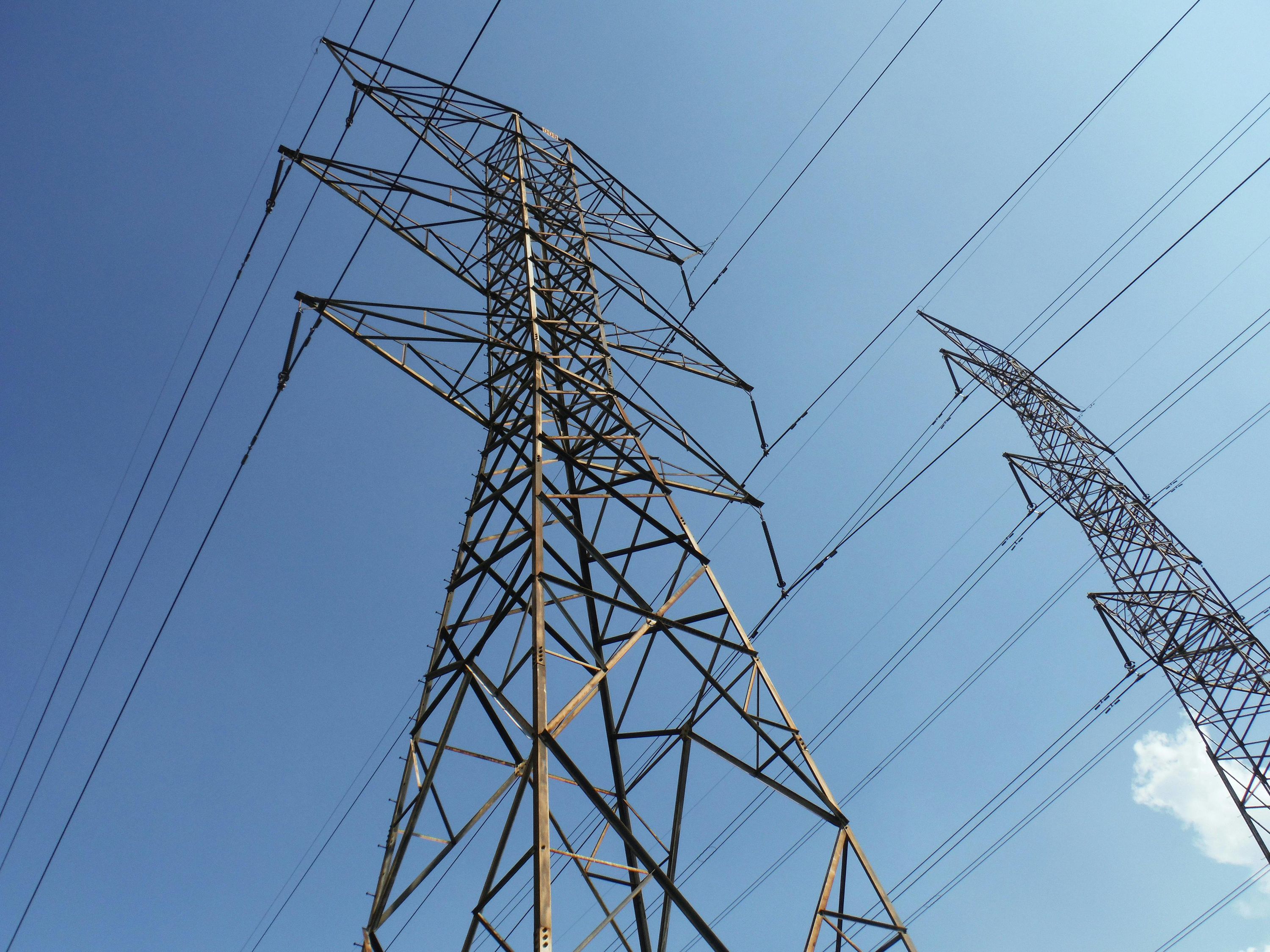
This is why long-distance power transmission uses very high voltages, sometimes hundreds of thousands of volts! This is also why Power over Ethernet (PoE) uses a relatively (for electronics) high voltage of 48 V nominal. Cat6 Ethernet cables typically use 23 AWG wire and Cat5e 24 AWG, this is fairly thin wire to be cost-effective, necessitating the use of higher voltage and lower current to efficiently transmit power. The twisted hook-up wire I used in many of my ManT1S demos is also 24 AWG.
What Did the Competition Do?
When you look at the Arduino UNO SPE Shield, you can see that it claims to support up to 48 W of power. However, it supports a maximum voltage of only 24 V. This means that if a node wants to actually use 48 W of power, it has to draw 2 A of current! This means large inductors and diodes, as you can see on that board, plus connectors and screw terminals that need to be rated to support this current. It also means that if you inject 24 V at one end of a 25 meter mixing segment and try to draw 2 A out the other end with 24 AWG wire, you’re going to lose almost 9 V along the way, and have only just over 15 V left at the load! 15 V at 2 A is only 30 W, not 48 W. You’re literally burning nearly 18 W in the wire. And you can’t really compensate for this loss by increasing the source voltage to 33 V, because when the load is not drawing this large current, the full voltage would reach the shield and destroy it due to over voltage.
So is this false advertising? Not exactly. After all, the above scenario is pretty much worse case. If you don’t need much power, you can go the distance using the Arduino UNO SPE Shield. Or if you do need the full 48 W power it can support, but only need to go a short distance, you will likely be OK. But it does show the engineering trade-offs that come into play and the limitations you may run into when the system doesn’t support higher voltages.
ManT1S power distribution
With the ManT1S, I decided to go in the other direction and learn from lessons that the industry learned over decades of PoE design and usage. Most PoE standards limit the current through a single twisted pair to 600 mA, while even high power Type 4 IEEE802.3bt is limited to 960 mA. All operate at relatively high voltages: 37 V ~ 57 V (48 V nominal) for the original IEEE802.3af standard, around 42 V ~ 57 V for higher-power standards such as IEEE802.3at and IEEE802.3bt. PoE needs to support up to 100 meters of cable but uses pairs in parallel, while T1S only has to support up to 25 meters but is limited to a single pair.
With all this in mind, the ManT1S was designed to keep the current low, 700 mA max, similar to PoE currents while supporting up to 75 V of input voltage. This is in line with what the industry expects to support over common twisted pair wire on the market, and by working along with this pre-existing limitation, the power carrying parts on the ManT1S such as inductors and diodes can also be kept small, allowing for high power in a small form factor.
Doing the same example calculation as in the previous section, the ManT1S can distribute the same 48 W of power by using a voltage of 69 V at roughly 700 mA of current. Considering the same 25 meter mixing segment using 24 AWG wire as before, you would lose only 3 V along the way. Because of the lower current, you only burn about 2 W in the wiring, so you actually can deliver 46 W to the load. And you can even compensate for the wire loss and get the full 48 W at the load by bumping the source voltage up to 72 V, which is still within the supported input voltage range and would not damage anything even if the full load was not present.
As you can see, by opting for higher voltage and lower current for power distribution, it is much easier for the ManT1S to maintain its advertised power capability across various use cases, even in worst case scenarios. One less thing for you to have to worry about!
What About the Low End of the Voltage Range?
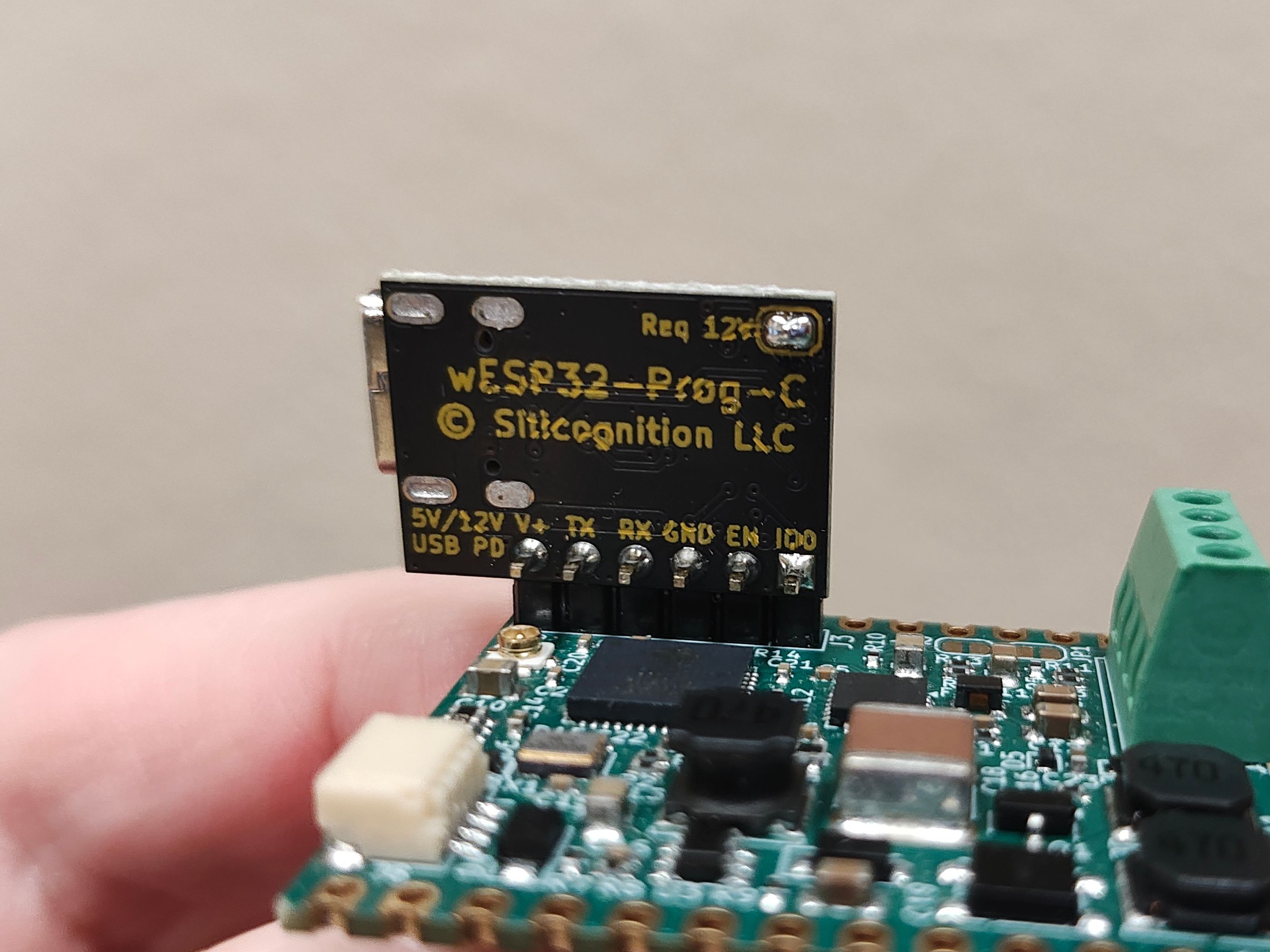
So if high voltage is the way to go, why is the ManT1S advertised as supporting 5 V to 75 V? Well, the ManT1S can be powered from 5 V. In fact, if you power a ManT1S from USB using the wESP32-Prog or wESP32-Prog-C programmer, it is running from 5 V by default. But it is not a good idea to distribute power to the whole mixing segment using 5 V. Unless you have really short distances and very low power requirements, remote nodes would see much less than 5 V due to diode and IR losses and would operate unreliably.
This is one of the reasons that the campaign offers the wESP32-Prog-C as a programmer accessory and not the original wESP32-Prog. The original micro-B programmer only supports 5 V output, while the newer wESP32-Prog-C supports Type-C Power Delivery and can be configured to request 12 V from a USB PD supply by bridging the solder bridge on the back.
With 12 V output, it can be used to power your mixing segment with up to about 13 W of power, which can support a development setup and low power applications. In a follow-up update, I will cover which connections to make on the ManT1S to use this 12 V USB PD power to provide power to the mixing segment, plus many more ways power can be applied to your ManT1S system!
Easy Power From the ManT1S-Bridge
When connected to a IEEE802.3at Class 4 PoE switch, the ManT1S-Bridge will request up to 30 W of power and will be provided with a voltage of 42.5 V to 57 V (48 V nominal) that can be used to power the mixing segment. For many use cases, this will be all the power you will ever need! And being a relatively high voltage, it is perfectly suitable to span the distance in production use.
But What if my Circuitry Requires a Lower Voltage?
The ManT1S already integrates an efficient power converter from the mixing segment voltage down to 3.3 V on board (available on the VDD pins). For modest loads (up to 1 A total for ManT1S + your application), this may be all you need. If your node requires a different voltage, there are various options. If your power requirements and/or distance between nodes are modest, it may be possible to use a relatively low mixing segment voltage such as 12 V and use it directly where needed. But for high power applications, using a high mixing segment voltage and down-converting it at the node is usually the better idea.
You do need to make sure that your DC/DC converter can handle the mixing segment voltage. This is relatively simple nowadays, various online stores offer low-cost modules with suitable input voltage ranges.
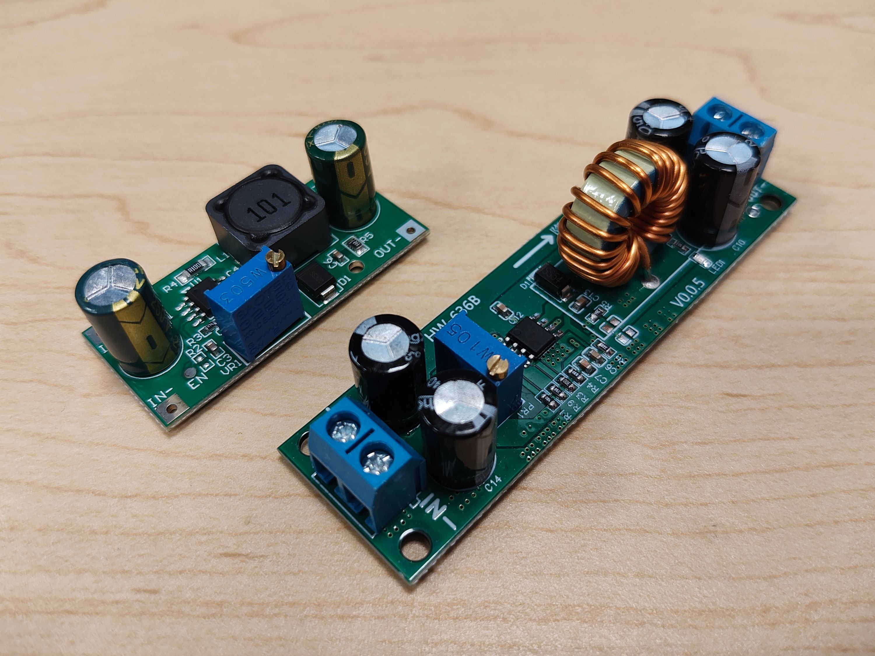
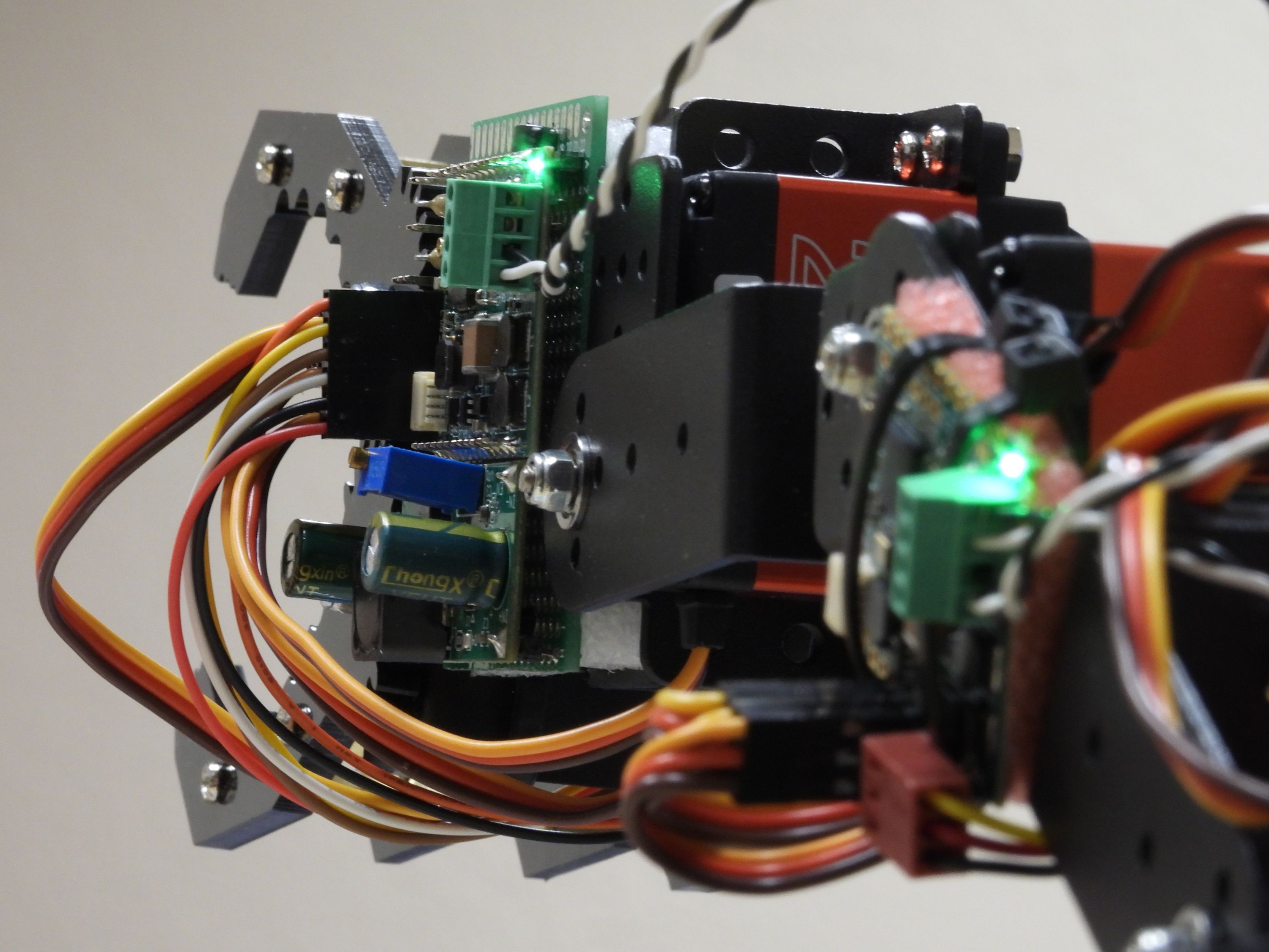
The campaign video robot arm demo uses this topology with local conversion at each node, because the peak load of the servos can be pretty high. The system is powered by the 48 V nominal PoE voltage from the ManT1S-Bridge and locally down-converted to the 6 ~ 7 V required by the servos at both the shoulder/elbow and wrist/claw control nodes. I used some of the low cost converters linked above to do the power conversion.
TL;DR: What is Recommended?
- For most low-to-medium power applications, powering the mixing segment from the ManT1S-Bridge connected to a PoE+ switch is a simple, ready-to-go solution that should be your default choice. Add local power conversion at each node as needed for your application voltages.
- If you need to distribute a high amount of power to remote nodes, go with a high mixing segment voltage and add local power conversion as needed.
- If one node of your system needs more power than the 52 W the ManT1S can distribute, it would be a good idea to inject power at that node and distribute power to lower power nodes from there.
- If you are making a system that also includes an Arduino UNO SPE Shield (or other nodes with limited voltage capability), make sure the mixing segment voltage is within the limits of all nodes. This may mean you can't power the mixing segment from PoE + ManT1S-Bridge.
- Remember that power can be injected at any node in the system, often a center node may be a better option than an end node if long distances need to be traversed.
- For low power and/or short distance applications, a wESP32-Prog-C configured to request 12 V from a USB PD power supply may be a simple way to provide power if you aren't using a ManT1S-Bridge and PoE.
- 5 V applied to V+ or supplied from a wESP32-Prog or wESP32-Prog-C is fine to power an individual ManT1S, but not suitable to power a mixing segment.
PS: Safety When Using Higher Voltages
After posting this update, a subscriber kindly reminded me that it would be a good idea to add a brief note about safety pertaining to the use of the relatively high voltages that can be used with the ManT1S. Since this is an engineering product, a certain level of familiarity with electronics is expected to effectively use it, but I agree the safety aspect should be mentioned nonetheless.
I use the term "relatively high voltages" in comparison to the voltages used in most common electronics that most campaign backers may be more used to. That said, the voltage range with which the ManT1S can be powered actually falls within the IEC 61140 extra-low voltage range. While people often reference 50 V as the upper limit of this range, it should be noted that this is the limit for AC RMS voltage. For DC, as used by the ManT1S, the extra-low voltage range upper limit is 120 V DC. The 75 V maximum voltage for the ManT1S mixing segment falls well within this range.
The extra-low voltage range carries a low risk of dangerous electric shock. That said, the exact risks depend on the power supply implementation and environmental factors such as wet or conductive conditions, and care should be taken with the relatively high amount of energy present (again in comparison to other electronics many users may be more familiar with). I would recommend reading the extra-low voltage article on Wikipedia for more context.