Project update 11 of 11
Orders Shipped and Jumper Board Fix
by Daniel GHi everyone,
Time for a major shipping update, and an interesting new issue.
Everything has shipped!
Everything has now been shipped out for final fulfillment! Many of you have already received your orders, and the remainder of them should be delivered soon.
If you have any issues with your shipment, like customs problems, or if any ordered items are missing, please contact Crowd Supply customer support, and they’ll help to get everything sorted out.
Technical support
With all hardware comes problems, and the TinyNES will be no exception. For any and all technical issues, please contact us at support@tall-dog.com and we’ll do everything we can to assist you and resolve the issue. So far, we’ve seen a bad power adapter, an improperly sized hex key, and a few other little things.
Also, please keep in mind that your TinyNES comes with a one year warranty. If something isn’t working right, or stops working, we’ll fix it or replace it at no cost to you if it’s within one year of your order being delivered. Even outside of this time period, please let us know and we’ll still do our best to help.
A new known issue, and the fix for it
We’ve discovered, and isolated, the first known issue with the TinyNES, and we’re already taking steps to mitigate it. We know this is affecting at least a few people, and even if it isn’t affecting you at the moment, you still might be interested in the details, or you might want to proactively protect against it anyway.
One of the main chips in the system is the PPU, or the picture processing unit, which is responsible for generating the video output. This is a 40-pin DIP (dual inline package) chip. Pins 14, 15, and 16 on this chip, also known as EXT0, EXT1, and EXT2, are typically not used. Technically, these signals could be used to allow two PPU chips to work together, but in a system like the TinyNES (and the original NES) which only has one PPU chip, these pins would be ignored and connected to ground.
However, the RGB variants of PPU chips use these pins for a different purpose: they output the red, green, and blue video signals directly. When we added RGB support to the TinyNES, we routed these signals to a small connector (H3 on the main board) which interfaces with the forthcoming RGB kit. Without the RGB kit installed, these pins don’t connect to anything, and this is where the issue arises. Prior to RGB support, these pins were simply grounded and they wouldn’t cause any problems. But when we added RGB support we also opened the door to this particular problem.
When a pin isn’t connected to anything, it’s referred to as "floating," and its electrical state is undefined. This is fine for an output pin, but not always the greatest for an input pin, and these particular unused pins can be used for both output and input in various circumstances. If they’re being used as input, and that input is floating, unexpected things can (and often do) happen.
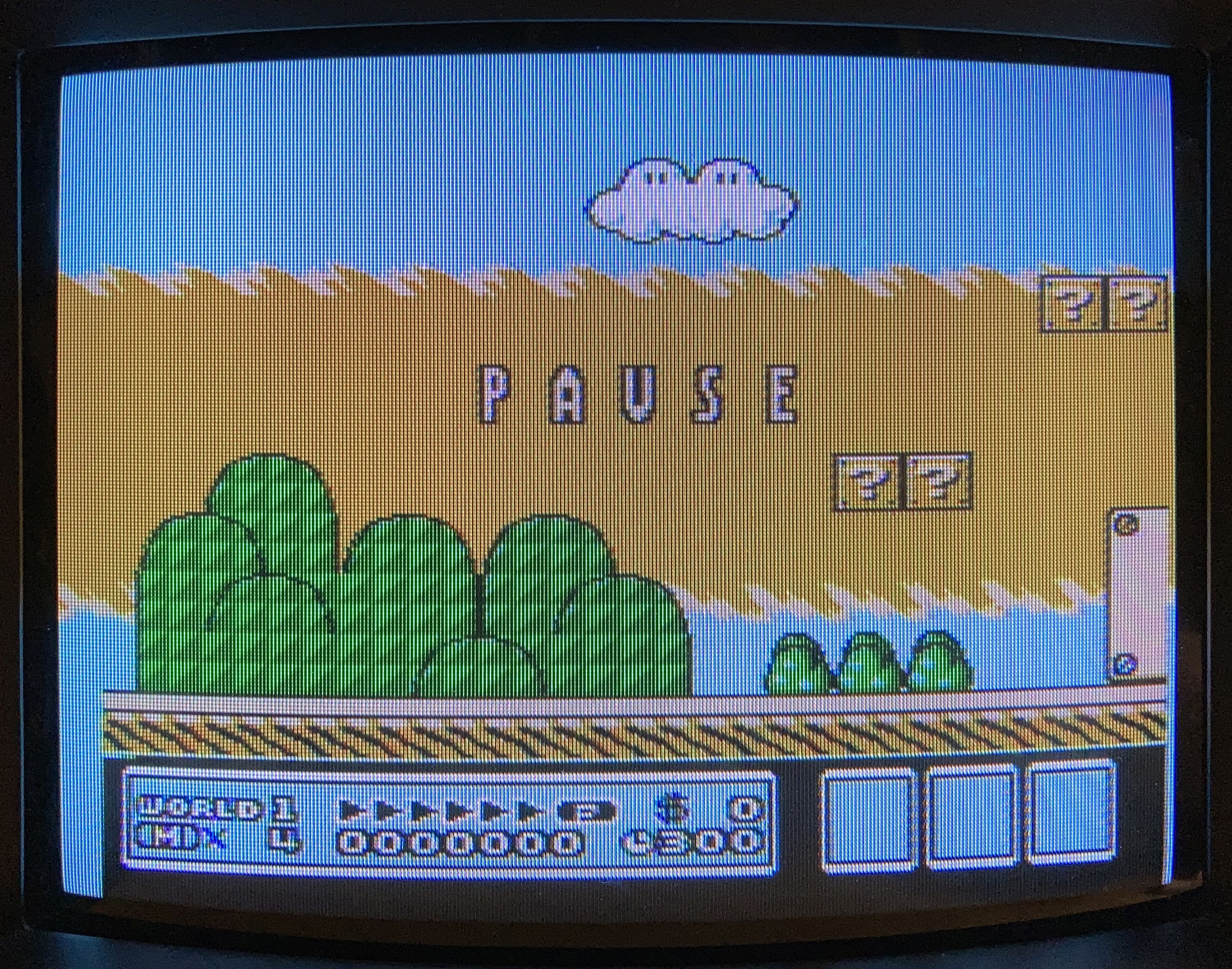
So, what kind of stuff might happen? This particular issue manifests as visual anomalies, usually color changes or flickering artifacts or bars in the background layer, when the system is handled or touched in particular ways near where the PPU chip is located. Human skin is somewhat conductive (this is how capacative touch screens work, just like the one on your smartphone) and tiny amounts of ambient capacitance can cause these floating pins to jump between values of high and low rapidly and unexpectedly. This is why some TinyNES systems may show visual issues when something (like your hand) comes in close proximity to the enclosure while a game is running.
For example, the sky in level 1-1 of Super Mario Bros. 3 should be solid blue, but here’s an example of what can happen when these pins experience some interference:
The good news is that there’s a simple and elegant way to fix this issue, even for existing systems where the main board would be cumbersome and expensive to modify or replace. A small jumper board can simply be socketed in the position where the RGB kit would otherwise be placed. This jumper board is very basic; it connects PPU pins 14, 15, and 16 to ground, and thereby completely eliminates this particular problem. An added small plastic spacer keeps it from becoming dislodged internally.
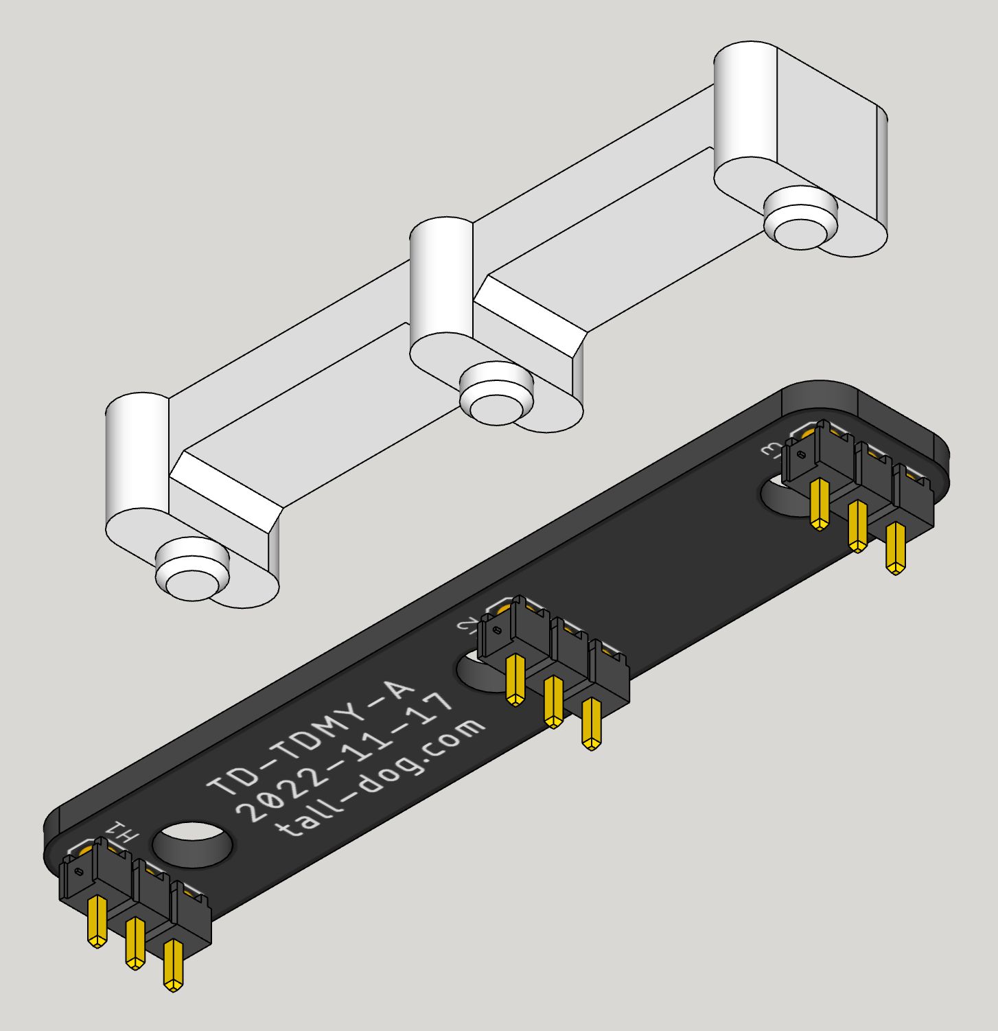
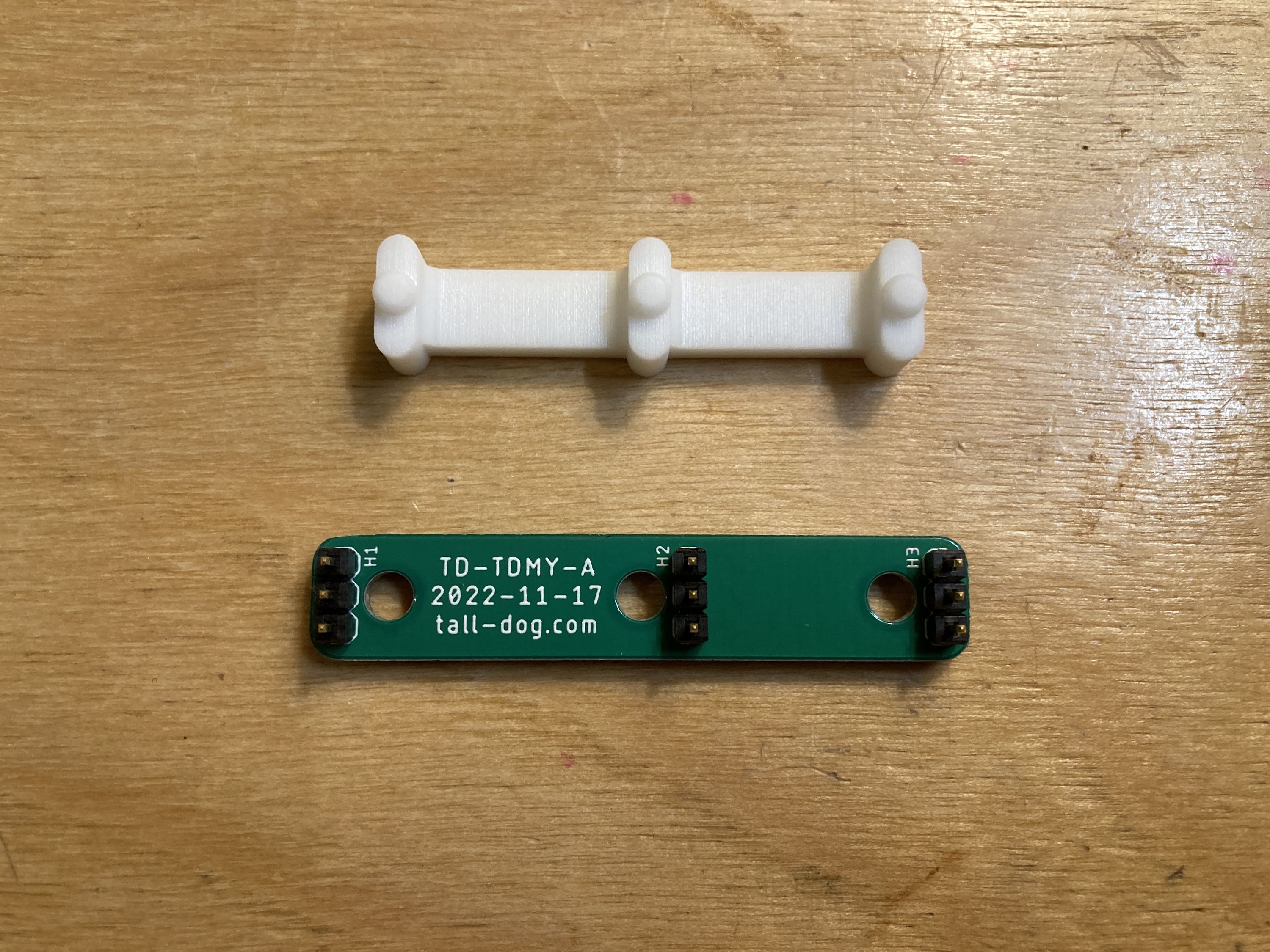
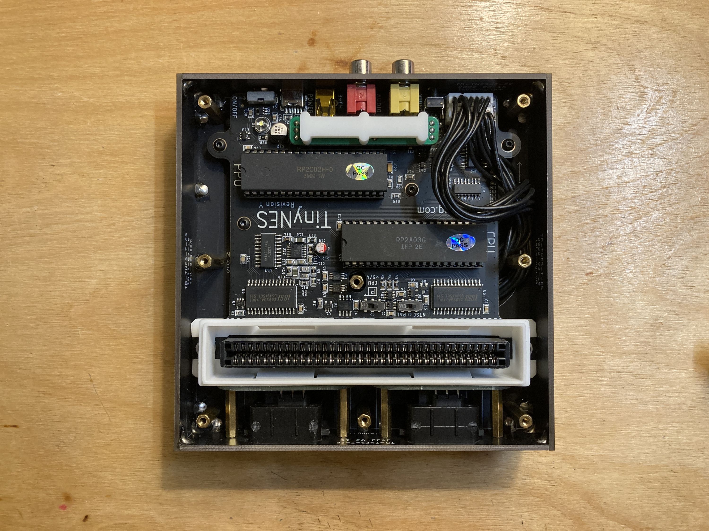
This board has already been designed and prototyped, and it works great. It’s small, cheap, and easy to produce. Installing it takes a few minutes and it doesn’t require any soldering, just removal of some top panel screws. We’ll provide this as a little kit to anyone who wants one, for free, and we have step-by-step instructions for you to follow as well.
To request your Jumper Board Kit right now, please fill out this form: https://forms.gle/97DipDf9UYr5dmbWA
You can also view the Jumper Board Kit assembly instructions here: https://talldog.dozuki.com/Guide/TinyNES+Jumper+Board+Installation/7
Oh boy, isn’t hardware fun? ;)
All the best,
Dan