Project update 7 of 11
Testing, Assembly, and Feature Updates!
by Daniel GHey everyone!
It’s been really busy here between doing assembly, design work, testing, and finding places to store everything as it arrives! There’s a lot to cover in this update, and it’s pretty much good news across the board, so let’s dive in.
Testing Updates
Our beta testers have had their pre-production units for a few weeks now, and a lot of new accessories and carts have been tested. Overall, the news is great, since pretty much everything works as it should. Here’s a partial list of new things that have been tested and confirmed to be working with the TinyNES:
- Zapper (light gun) with a CRT monitor (which is always required because of lag associated with LCD monitors)
- Arkanoid / Vaus controller
- Four Score (4-player adapter) with controller extension cables (these are required to make the physical connection)
- Miracle Piano Teaching System
- Game Genie (which is a bit physically awkward, but it works)
- Krzysio Cart, NES version (flash cart)
- Haradius Zero (cart)
- Trophy (cart)
- Project Blue (cart)
- Jeffrey Wittenhagen's Black Box Challenge (cart)
- Supervision 52-in-1 (multi-cart) (*)
- Goofy Foot (MP3 audio cart) which uses a Membler Industries Cheapocabra GT-MP3-01 board
- 8-BIT XMAS 2016 (cart)
- Ploid (NESMaker cart)
- Doodle World (NESMaker cart)
- Arm Wrestling Classic (NESMaker cart) (*)
- Dungeons and Doomknights (NESMaker cart) (*)
(*) These starred items have exhibited some potential issues, but only with particular CPU chips. This behavior is being investigated further at the moment.
We also now have some initial quantified data regarding the quality of the TinyNES audio path, and the results are good so far. The noise floor is lower than the NES-001 (front loader) and the individual audio channels are nice and clean.
Production Status
All Famicom Adapters have now been assembled, packed, and shipped to Mouser!
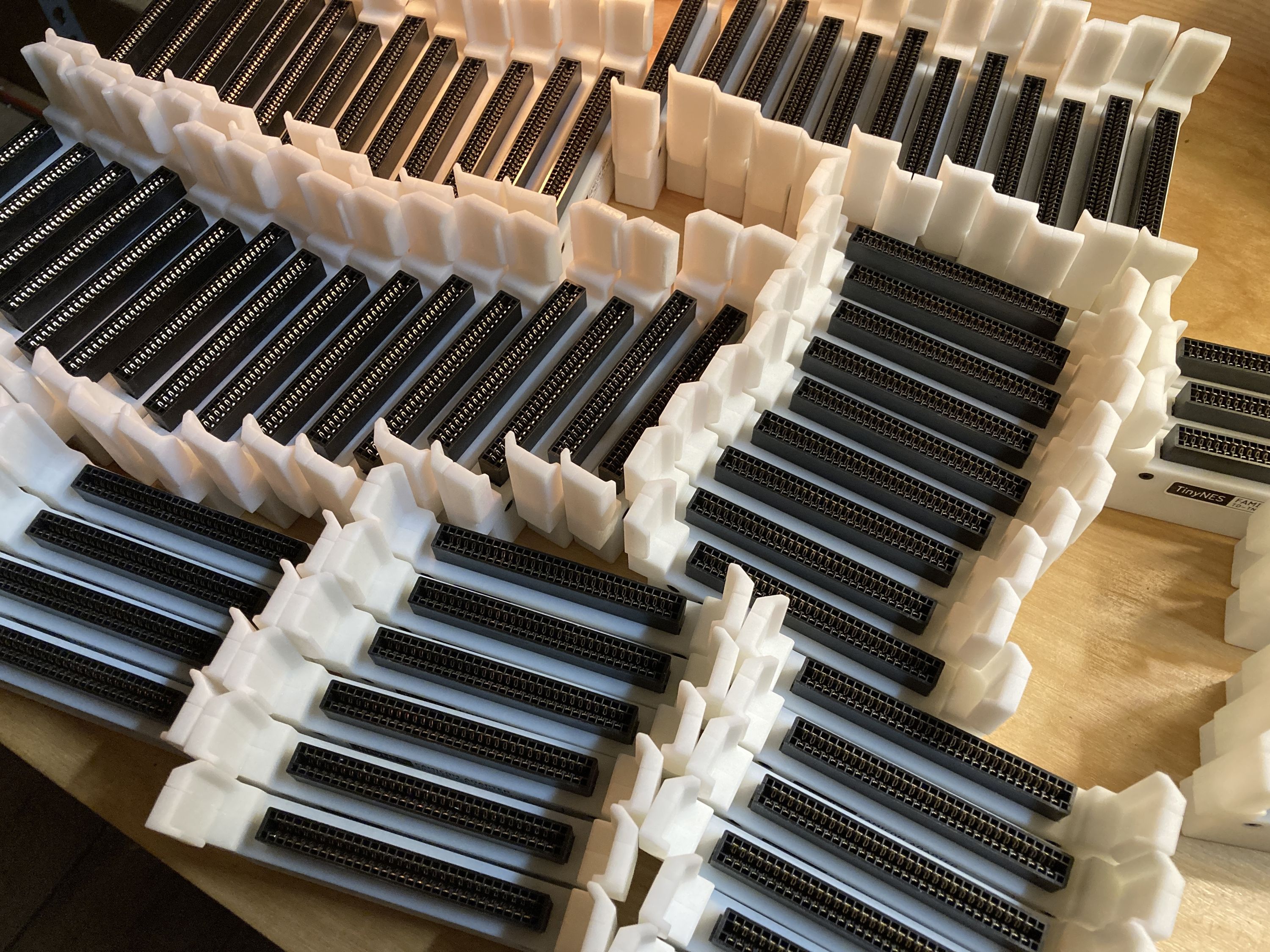
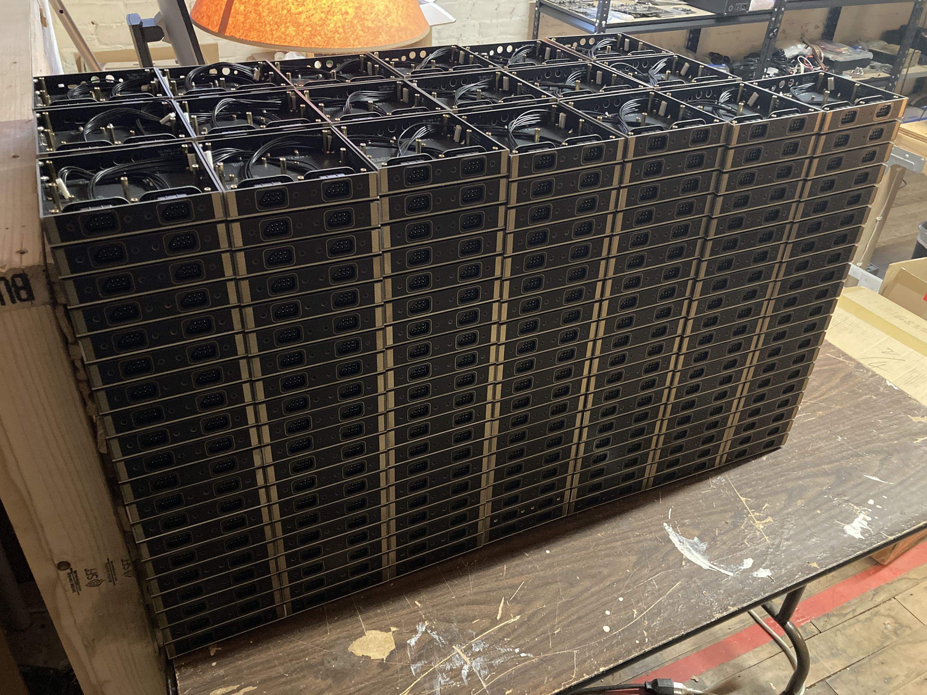
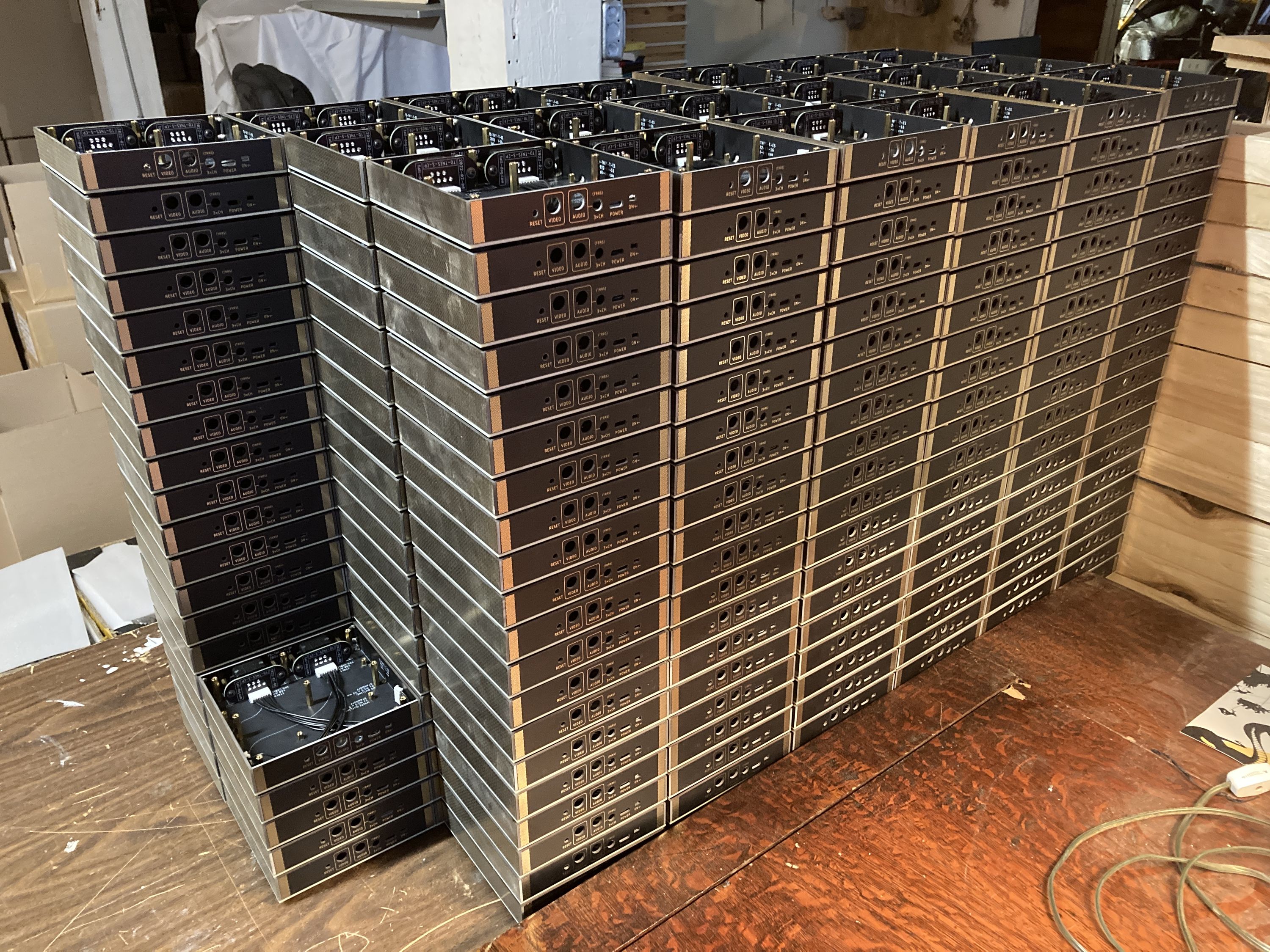
All TinyNES console enclosures have been assembled and are ready for main boards and final assembly!
Finally, all the foam packaging inserts have been received, and they look good.
PowerPak Support
Thanks to the excellent work of one of our beta testers (Jeff from Marshall Art) the issue preventing the RetroUSB PowerPak from working has finally been fixed! This means that the PowerPak, a CF-based flash cart, now works beautifully with the TinyNES. This also means that the number of known incompatible carts has been reduced to zero (aside from the occasional ones with weird pins which don’t work for physical reasons).
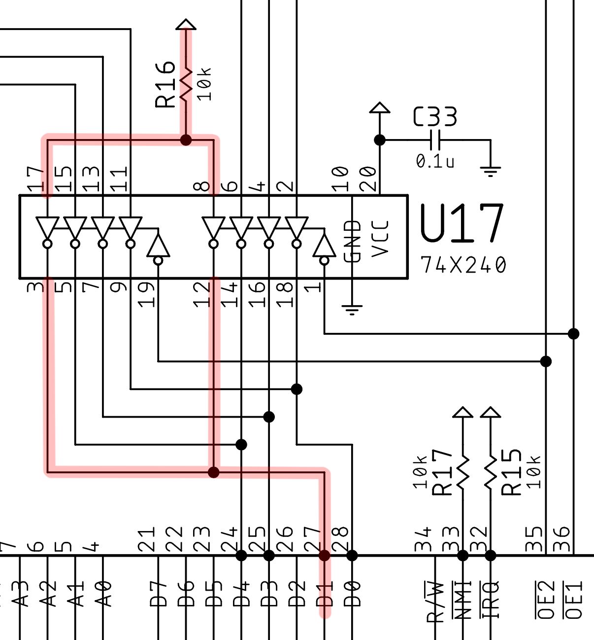
What was the issue? It turns out that the PowerPak polls the status of the D1 line, which is normally not used. In an original NES, this line is connected to the expansion port and that’s about it. Anyway, the PowerPak checks to see if this line is low, but in the TinyNES, it was left floating (side note, the D2 line is still left floating, which is okay). One resistor was added to the circuit, and now the PowerPak works great.
Note that the PowerPak still might be a little pickier about particular CF card models when using it with the TinyNES. Most of the ones we’ve tested have worked, but one or two have not, and this may have to do with bursts of power consumption that vary between different CF cards. Also, note that the PowerPak isn’t compatible with all CF cards to begin with.
Expansion Audio Mix
We hoped that a consistent level for expansion audio would suffice for the variety of carts out there, but we were wrong! In the course of additional testing, we found that the appropriate level for different carts just varies too widely for a fixed mix level to work in all cases.
Why is this a problem in the first place? Famicom carts typically perform the final audio mix themselves. On a real Famicom, the cartridge connector (and corresponding Famicom cart) each have dedicated pins for audio input and output. The cart gets audio from the CPU, then can do whatever it wants to that audio before spitting it back out, including mixing in its own additional audio from whatever the designers could cram into the cart. This allowed the game to mix in its own extra audio at whatever level it wanted to.
Notably, this is not how the NES functions. NES carts don’t have the audio input / output pins that Famicom carts do. So how does the TinyNES (or a modded original NES) support expansion audio? We pick one of the cartridge connector pins that’s not used (EXP6 in this case) and use it as our audio input pin (for audio coming from the cart). The Famicom adapter or flash cart being used has to support this (our Famicom adapter does, as does nearly every flash cart). A Famicom game will still dutifully mix its additional audio with whatever it gets, which in this case is nothing. Then it spits that out on its audio out pin, which the adapter routes to EXP6. The system still needs to mix that with the regular CPU audio channels, and this is where we run into our problem. Instead of the Famicom cart doing its own mixing at whatever level it wants to, the system itself has to do the final mix.
The easy (and common) solution for this is to allow the user to somehow set the mix level manually to be whatever sounds good. For most people who are using only one or two Famicom games with expansion audio, or who are usually only using one flash cart, they’ll probably rarely (or never) need to adjust the level. Some flash carts, like the EverDrive N8 PRO for example, let you set the mix on the cart, and it even has different preset levels for different audio chips.
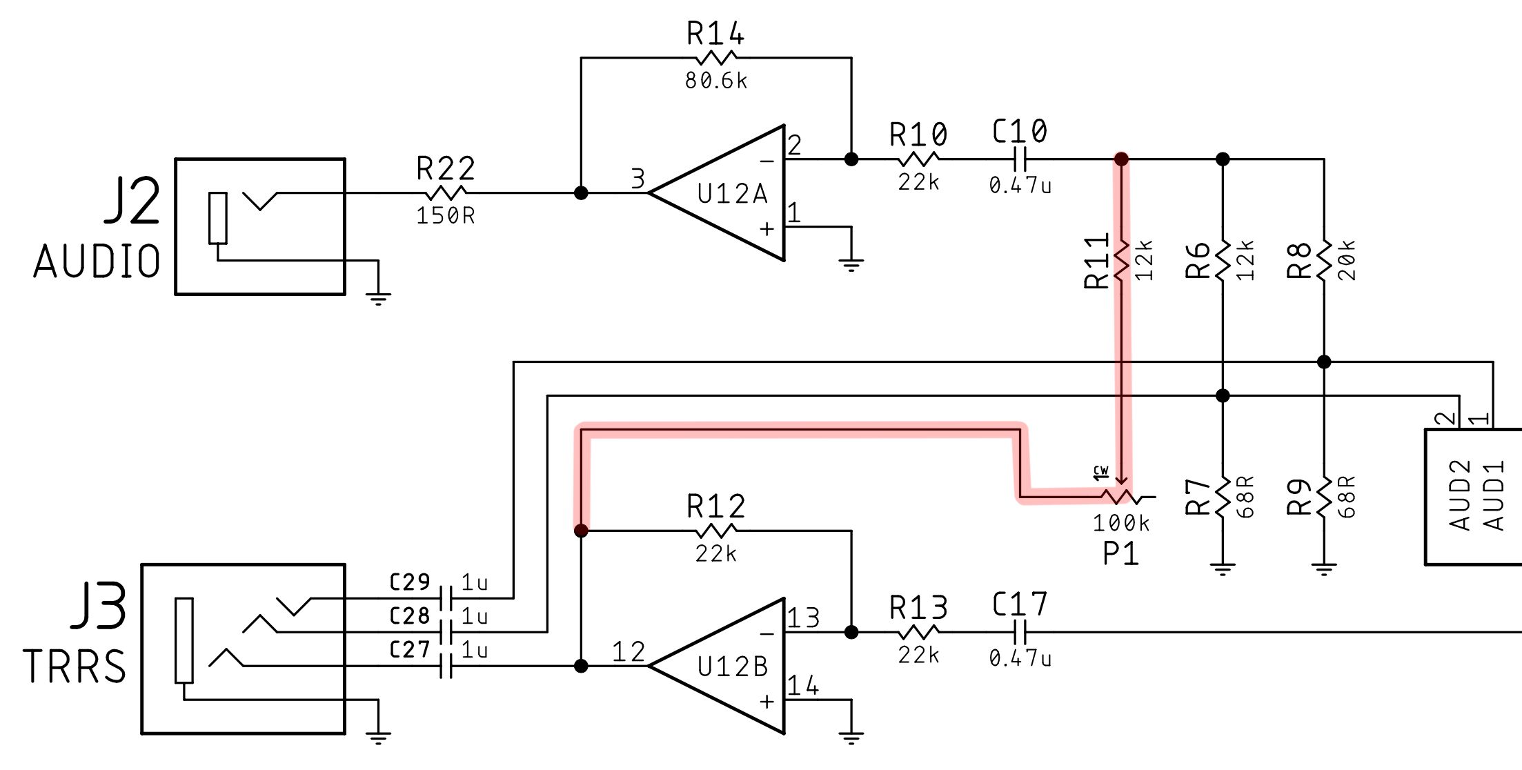
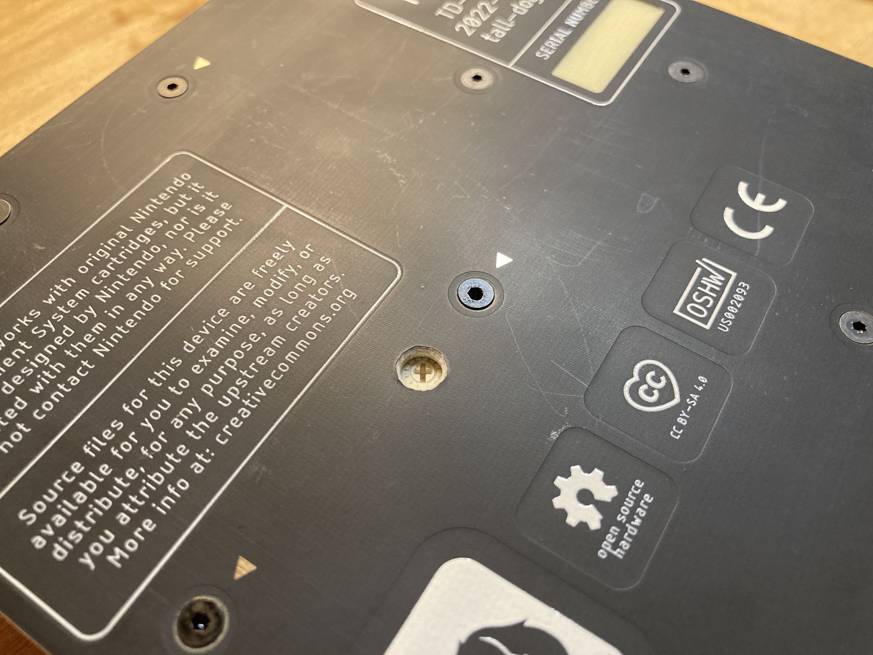
However, to make sure that expansion audio can sound good on the TinyNES in all situations, we’re adding a little trimpot that’s accessible via the bottom of the console. This trimmer will set the mix level of the expansion audio (EXP6) channel to anywhere between 12 k and 112 k, relative to the internal CPU AUDIO1 (20 k) and AUDIO2 (12 k) channels. A small price to pay for all carts being able to sound awesome!
This also means that we have to drill an extra little hole in every single one of the enclosures!
PAL Support
We’ve added support for PAL region games and video output (specifically PAL-B, which is the most common PAL variant). This is an exciting development, but there are still some important things to take into consideration! Most importantly, TinyNES units won’t support PAL right out of the box. This is because, by default, they will ship with an NTSC pair of chips (whether or not you opt for genuine or clone chips, they’re still NTSC). These are the RP2A03 / UA6527 and RP2C02 / UA6528 which run at NTSC clock speeds and output NTSC video. However, these chips are socketed, so they can easily be swapped out for different chips.
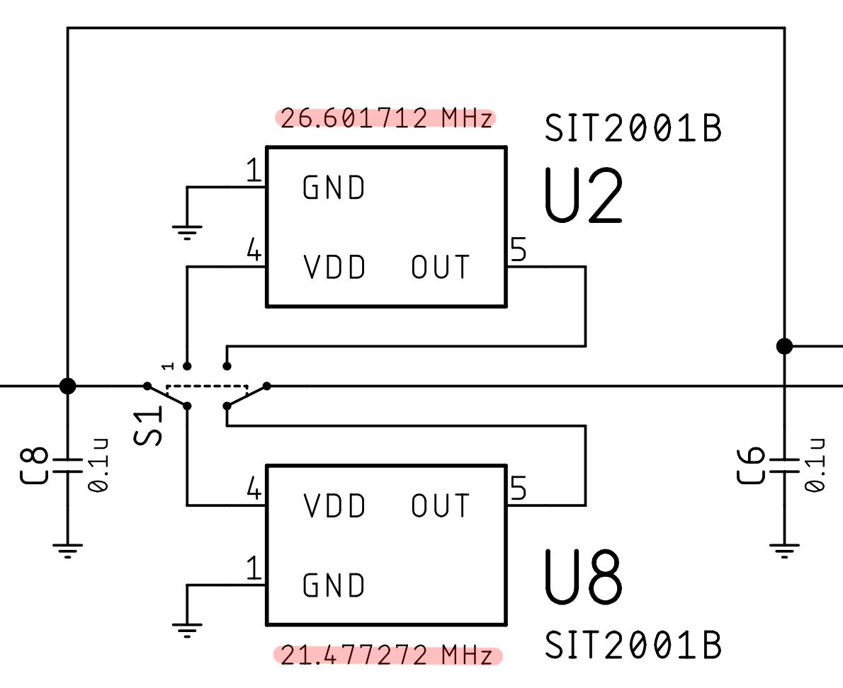
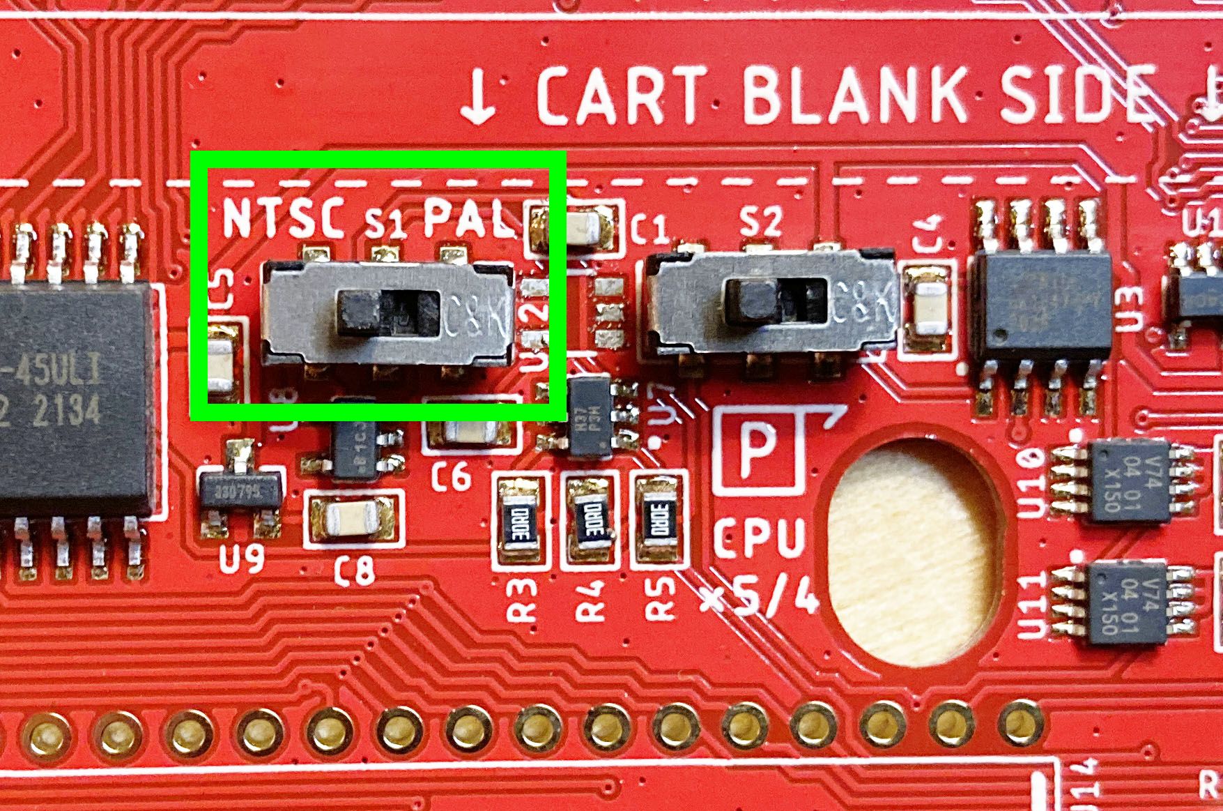
This is where the PAL support comes in. PAL requires several changes to the system. First, a different set of chips are needed, and second, a different master clock speed is required. To facilitate PAL support, we’re actually adding a second MEMS oscillator onto the TinyNES main board, and an extra little switch to choose between PAL or NTSC. One clock runs at exactly 21.477272 MHz for NTSC (this is the default setting), the other runs at exactly 26.601712 MHz for PAL, and only one of these oscillators will be active at a time.
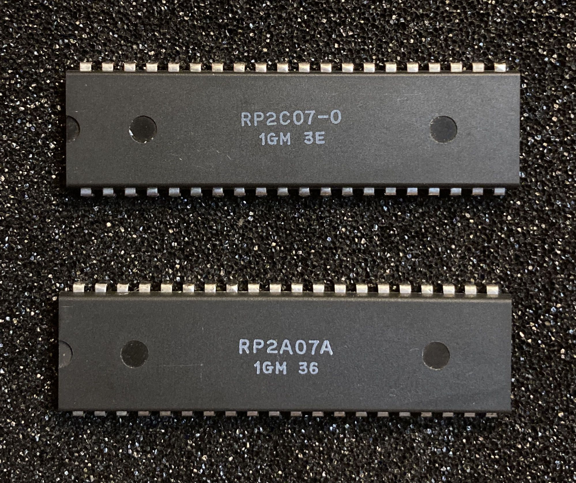
The big caveat here is that for PAL support, you’ll have to provide your own set of chips (CPU and PPU). It’s easy to socket them into the system, and opening it up to do so (and to flip the little switch) is also very easy. For the moment, we don’t have an option to purchase a TinyNES console that comes with a set of PAL chips, so you’ll have to already have a set of them or find them to purchase on your own. The necessary PAL-B chips are the RP2A07 / UA6540 for the CPU and the RP2C07 / UA6541 for the PPU.
RGB Support
RGB video was the most-requested TinyNES feature during the fundraising campaign, and while we’d love to natively support RGB out of the box for everyone, that’s just not in the cards. However, I think this solution is a lot better than nothing, and it should at least make a handful of people happy!
Similar to PAL support, the TinyNES won’t output RGB video out of the box. However, it is going to have support for RGB output with some additional requirements (but no permanent modifications or soldering). First, one necessary (rather expensive) component needs to be provided by the user, and second, a relatively inexpensive kit from us will also be needed. Let me explain how this works in some more detail.
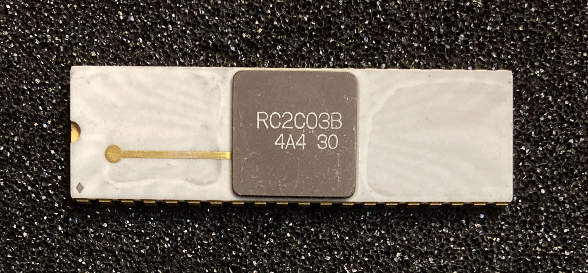
What we’re doing is simply facilitating the use of certain RGB PPU chips. These chips are the RP2C03 and RC2C03, which are the recommended versions because they output (more or less) the same color palettes that one would expect for most NES games. The RP2C03 (plastic) is slightly more accurate than the RC2C03 (ceramic) but the differences are minor. All RP2C04 chip variants will function too, but each of them have vastly altered palettes, so most games will simply look totally weird with them. RP2C05 chips aren’t supported at the moment because of some internal differences.
A quick warning: RP2C03 / RC2C03 chips are hard to find and they’re expensive. These chips were manufactured for use in arcade and specialty machines (eg. the VS. System, PlayChoice-10, Famicom Titler, and so on). You can expect to pay well over $100 for one of these chips, if you can find one for sale. For this reason, we can’t sell TinyNES systems with them. So you’ll have to already have a chip on hand or find one out there to buy if you want RGB video. Also, please note that the aluminum heatsink found on some of these PPU chips won’t fit within the TinyNES enclosure so it will need to be removed (a heat gun works well) and optionally replaced with a shorter one. The good news is that these chips were almost always socketed to begin with, so the ones that exist usually haven’t ever been soldered and are in pretty good shape.
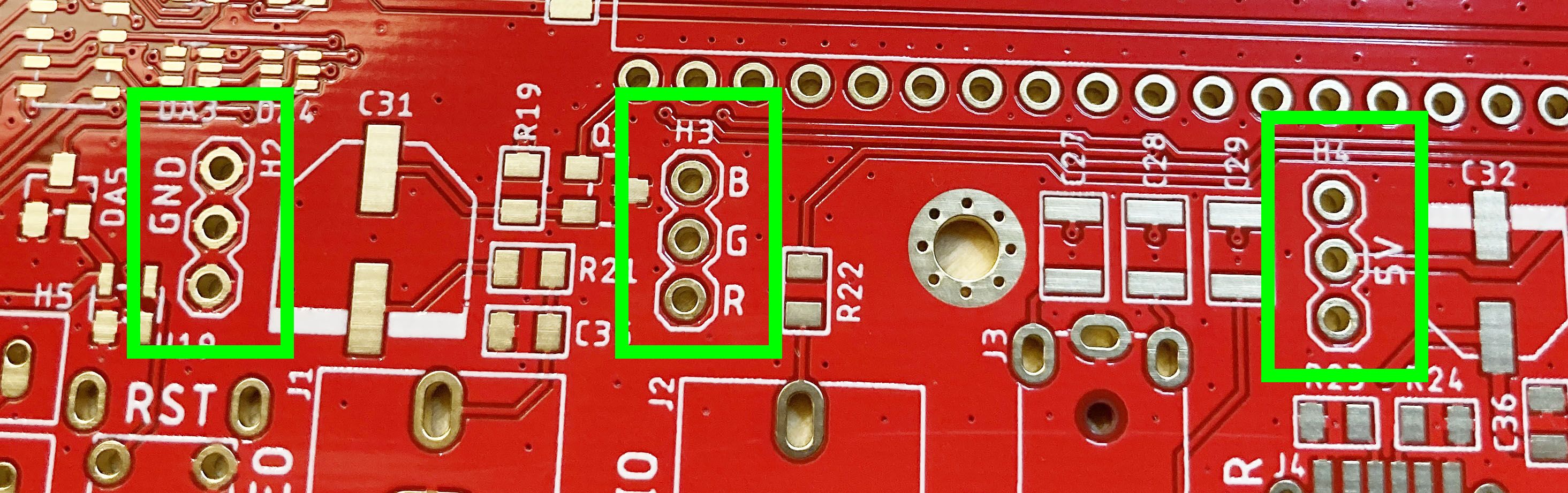
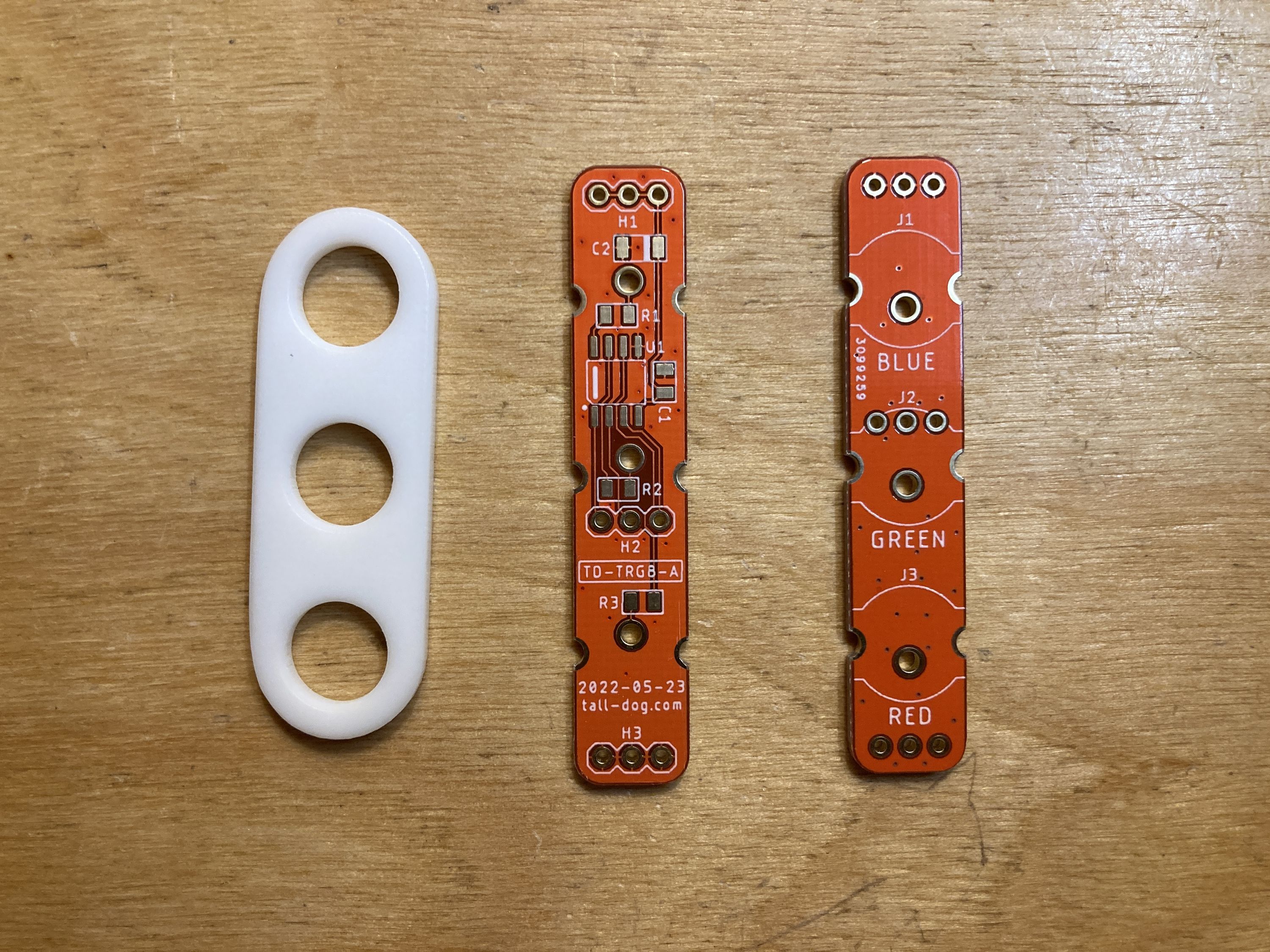
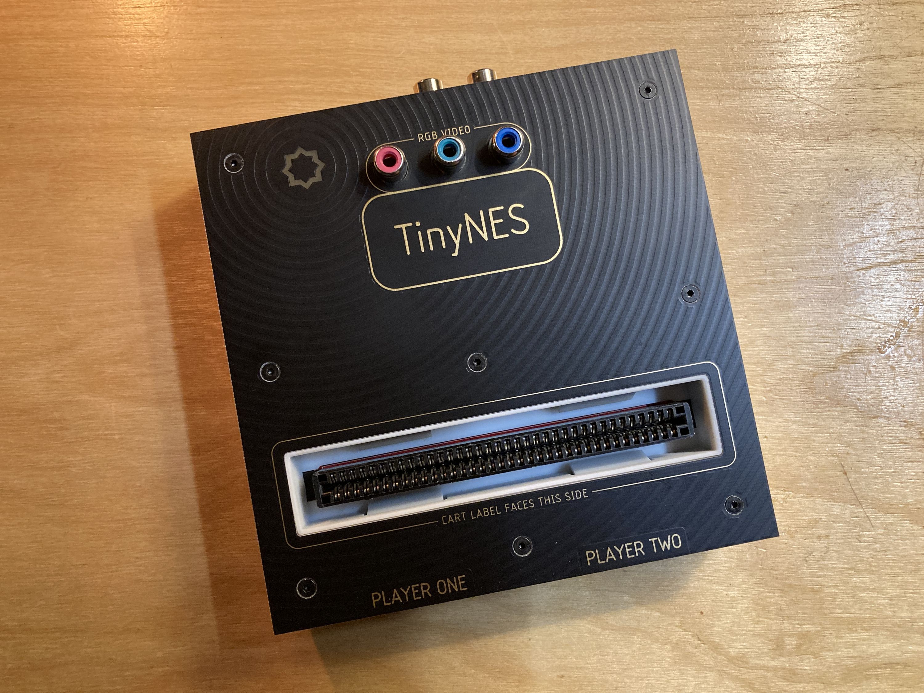
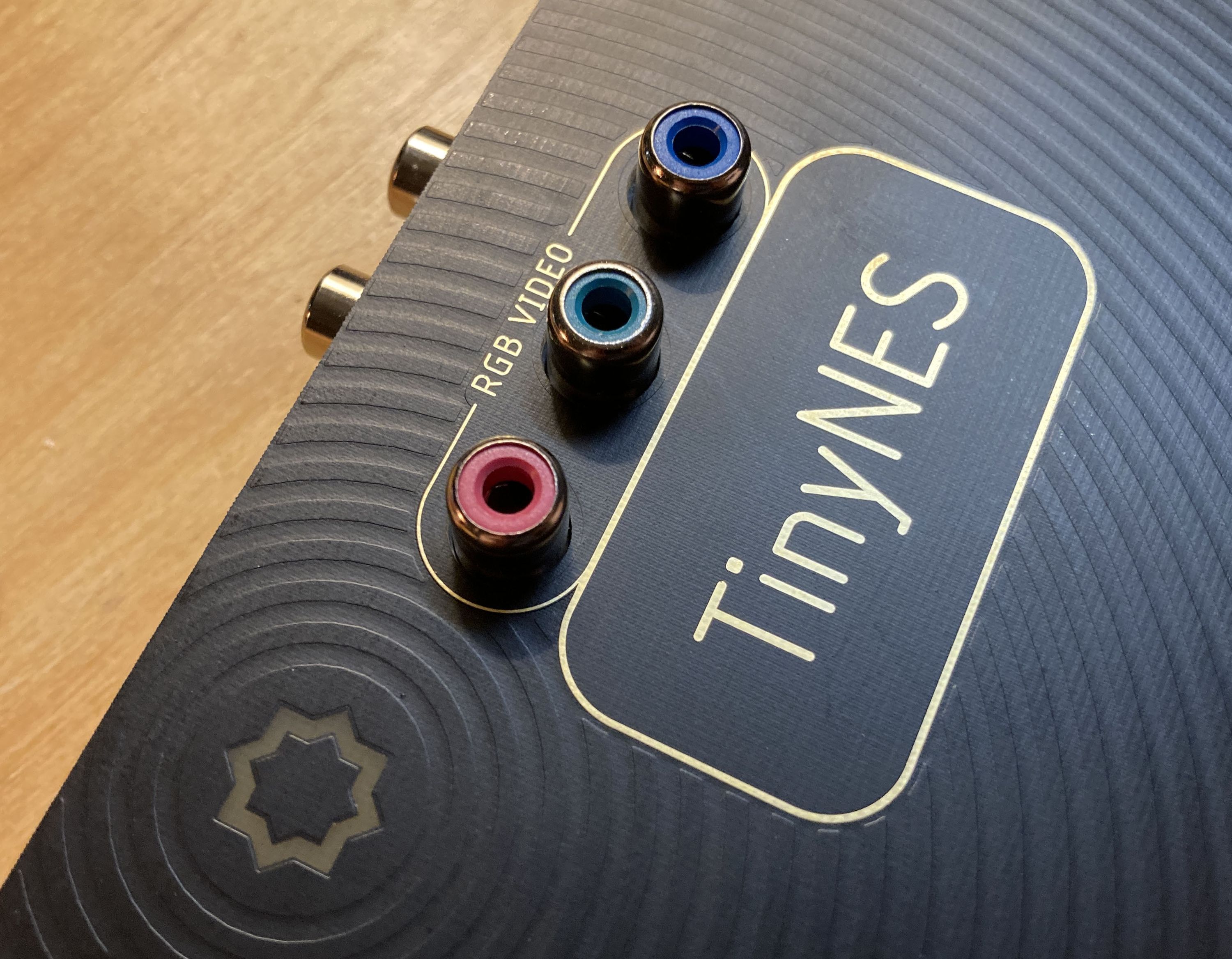
You’ll also need an RGB kit from us (which will be assembled with all components, even though the pictures above are not). We haven’t nailed down the price, but it won’t cost very much, probably somewhere in the $25-35 range. This kit will include a little board that sockets into the TinyNES main board that adds amplification for each RGB signal and physical RCA connectors for the three video channels. The kit also comes with a replacement top cover for the TinyNES enclosure that has the appropriate holes and markings for the RGB connections.
RGB Video Output Formats
Finally, I want to bring up something of an open question, specifically about RGB output.
The output from the above RGB solution is true RGBS output. This means that there are three analog video signals representing the red (R), green (G), and blue (B) parts of the image. There’s also a necessary sync (S) signal output via the yellow RCA connector on the back that would otherwise be used for composite video. The sync signal is what’s called "composite sync" which means that it’s actually a combination of the horizontal (H) and vertical (V) sync signals. Hence, there are four signals in total: RGBS.
In order to display this, one would need a monitor that can accept RGBS input via four discrete connections. These exist, but they’re not especially common. They’re primarily arcade monitors as well as older broadcast television studio monitors. Or, one could try and convert the signal into something else without losing quality or introducing lag.
The first option for conversion is certain (mostly Sony) monitors that accept something called RGsB, which is very similar to RGBS, but instead of the sync being discrete it’s carried on the green (G) signal. This is also called "sync on green" (or SoG) at times. Getting the sync signal onto the green channel isn’t very complicated, but it’s presence can alter the appearance on an RGBS monitor, so it can’t be done by default (it has to be optional).
The second option for conversion is VGA monitors, which are quite common. VGA uses these same RGB signals, but instead of a composite sync, it requires separate H and V sync signals, so this format is called RGBHV. Converting the native composite sync (S) signal back into its constituent parts (separate H and V) is possible, but requires some processing. Some potential options for this are LM1881 or GS4981 chips. Also, a very common Chinese board called the GBS-8220 (about $30 on eBay) is capable of doing this conversion, but it would require some careful wiring (we could consider making a custom cable that would make it super easy).
The third option for conversion is modern televisions that have "component video" inputs. These are usually RCA jacks that may be colored red, green, and blue, but these are not actually RGB inputs! Instead, they’re something called YPbPr, which is somewhat similar to RGBS, but not identical. In this format, there are still three video signals, but instead of straight RGB they’re split into luminance aka luma (Y), the difference between blue and luma (Pb), and the difference between red and luma (Pr). Furthermore, the sync (S) signal is carried on the luma (Y) channel instead of being separate. The board mentioned above (GBS-8220) can do this conversion, as well as another little Chinese board that appears to have all the necessary connections as RCA jacks (https://www.ebay.com/itm/115391663532) as well as SCART connectors (which aren’t really used outside of Europe). We’re hoping to test it out.
For more information, please see:
https://en.wikipedia.org/wiki/Component_video
https://en.wikipedia.org/wiki/YPbPr
So, my main question at the moment, is how much (if any) conversion should be built into our TinyNES RGB kit?
- A) None. This is the current state. True R, G, and B are output from the extra RCA jacks, and S is output from the rear yellow jack. The user is responsible for any further conversion.
- B) SoG option. This would add the option via an internal switch of combining sync (S) onto the G (green) channel, which would expand use to monitors that require this.
- C) SoG and YPbPr options. This would add yet another internal switch which would also provide the option of native YPbPr output for component video monitors and televisions.
- D) SoG, YPbPr, and VGA options. Same as above but also giving the options to split sync into separate H and V signals. I'm not sure how this would be output in terms of connectors, since 2 additional jacks (or an actual VGA connector) would be required, so this would require some physical redesign in addition to the circuit itself.
Right now I’m leaning toward A or C, but I’d love to hear feedback, so please let us know if you have any thoughts or suggestions about this!
The End
Phew, that was a long update.
As always, if you have any questions, please let us know!
All the best,
Dan