Project update 3 of 13
Board Details and Updates
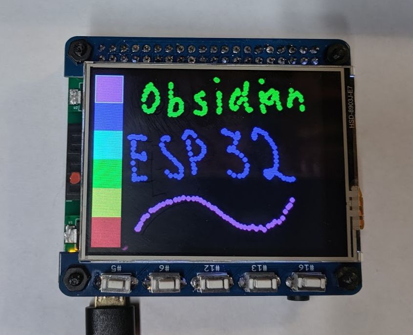
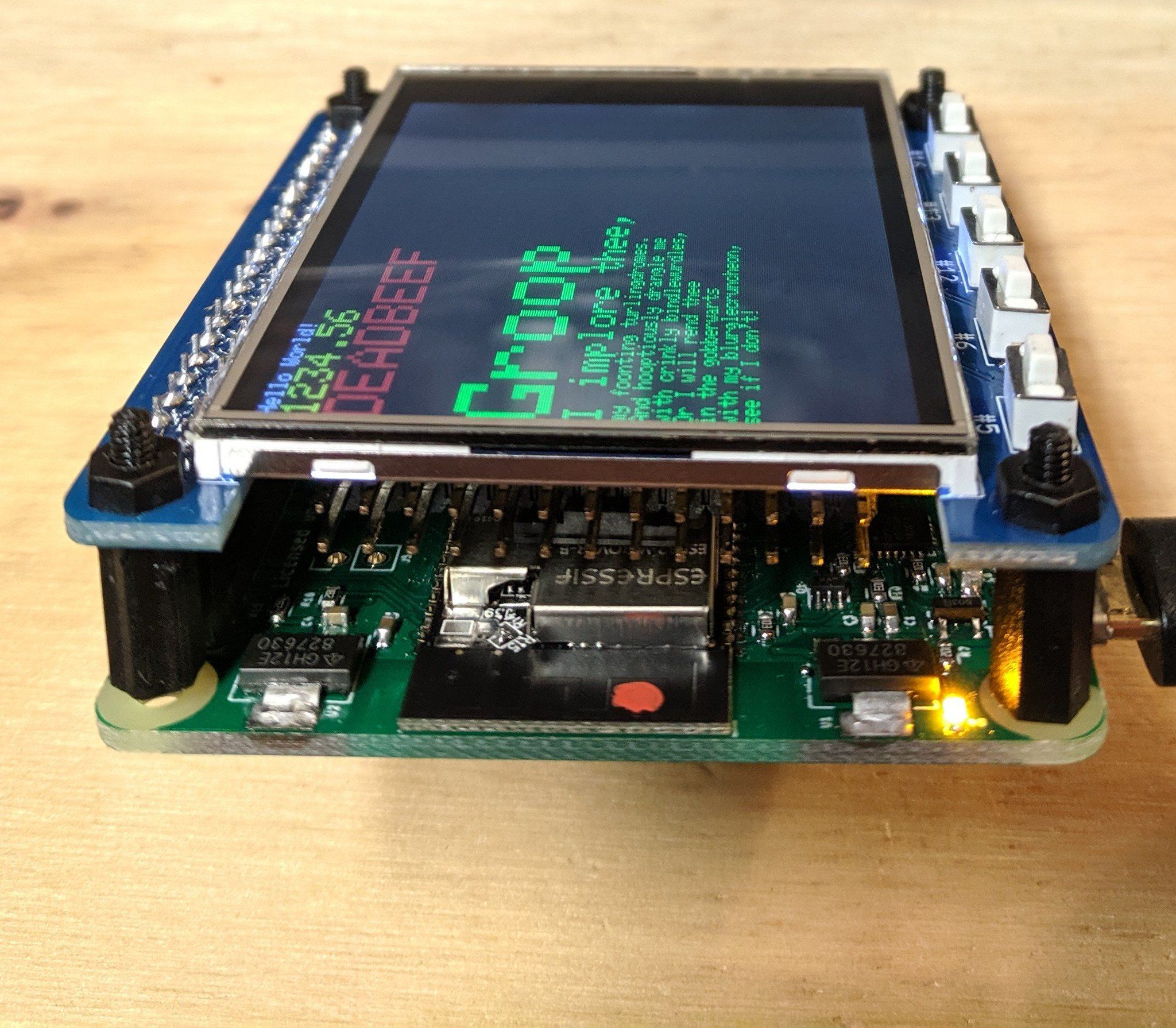
The last week has been primarily a wait for components while testing various features and double-checking schematics. The new PCB’s arrived from PCBWay right on schedule, and I assembled one the same day. I’m pleased to announce the adjustments to support the RPi display HAT’s was successful, and the other adjustments made look great.
Some things that are immediately noticeable:
- The use of an SOIC package instead of an SSOP on the I/O expander.
- The larger clearance around the WiFi antenna
- Some component adjustments in the power/USB area
- The green PCB
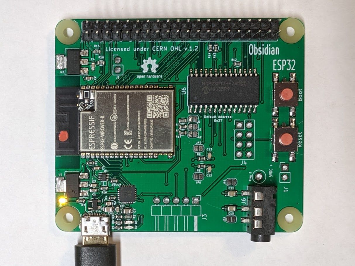
To address the least serious, the green PCB was accidental, but it will be helpful with some traceability on the prototypes, beyond the revision date on the back. Production intent will still be black.
The small component adjustments were in response to moving the regulator and LED downward, I decided to spend a little time cleaning up the routing all over the board. There are still some routes that could use an adjustment, however I’m much happier with this configuration than I was with the last.
A few questions came in, both here and on Twitter, concerning the components near the antenna. I had the area available to make some adjustments here, and while I haven’t noticed a performance issue, I agree more clearance is better.
The switch to an SOIC is a bit more interesting. I had originally used the SSOP because I wanted to use the least amount of board space, thinking that would be the best direction. I can safely say that is a wrong assumption, routing the traces around that tight-pitch components was a pain, and resulted in a bit of a mess layout wise, and was the most difficult to solder component on the board (a close second would be the micro USB). With the SOIC package, I can run traces between the pads, making routing in general a far less painful and messy experience, and it is easier to solder and place.
Now to discuss some of the so-far not discussed parts of the board.
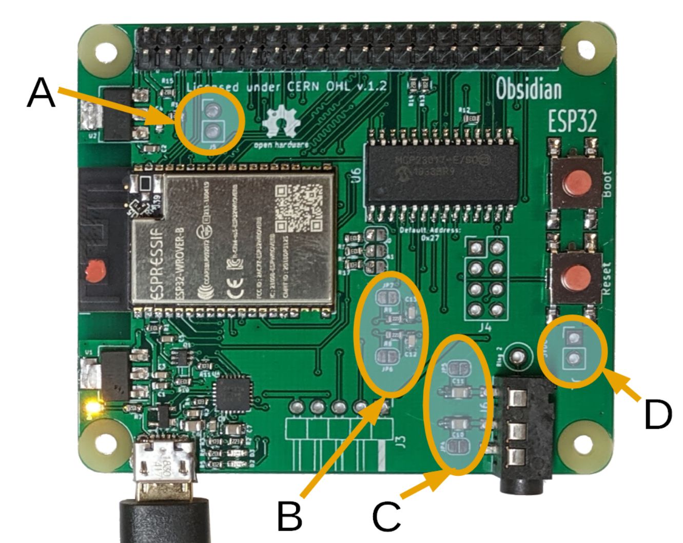
A) This header is non-functional on the WROVER based Obsidian ESP32 boards. If the PCB were populated with a WROOM32, this would be GPIO 16 and 17
B) This area of the board is a low-pass filter to help squash some of the noise inherent with using an 8-bit DAC to produce sound. The solder jumpers are present to allow the user to bypass the 220 ohm resistor if the DAC is to be used for non-audio purposes
C) More of the audio circuit, these large capacitors are to remove the DC component from the generated audio signal from the DACs. These too can be bypassed via the solder jumper pads on the board
D) 5V power. This is intended to be an input, the holes are 2.54 mm spaced to use standard jumpers or small 2.54 mm screw terminals. There is no electrical separation between this and the USB, it can also be used as an output for small peripherals, keeping in mind the limitations of the micro-USB powering the device.
I did not label it, but directly behind the TRS jack is a pad to allow access to the 2nd ring from the connector.
Back to the display hat, the touch controller works as well: