Project update 2 of 9
First Update and Test-Jig Development
General Updates
First, I want to thank everyone for pledging and following the TinyFPGA BX project. The amount of support the project is receiving is great and makes it that much more fun to work on. The original TinyFPGA B2 production run was 250 boards and the new BX campaign has pledges for nearly that many at the time of writing this update. Thank You!
The TinyFPGA BX is an open hardware project, you can now find the source files at the TinyFPGA BX GitHub repository. This is the first release of the BX source files and there will be updates later for the project templates.
The open source USB bootloader used by the TinyFPGA BX can be found at the TinyFPGA Bootloader GitHub repository.
Test-Jig Assembly
Besides developing the TinyFPGA BX board itself, supporting even a small production run of boards requires a dedicated testing and programming jig. While the bare PCBs are fully tested at the factory, the assembled boards require functional testing and programming of the bootloader and unique ID. In order for me to test every board in a reasonable amount of time I need a dedicated test-jig.
The original B2 board had a simple test-jig that operated by pushing a board down on the pogo-pin contacts by hand.
The new BX has a different pinout requiring nearly twice as many pogo-pins. The BX test-jig would require a toggle clamp to hold the board firmly against the pogo-pins. It also requires a new PCB design to accommodate the new pinout and increased number of IOs to test. However, the tester firmware and microcontroller could be reused.
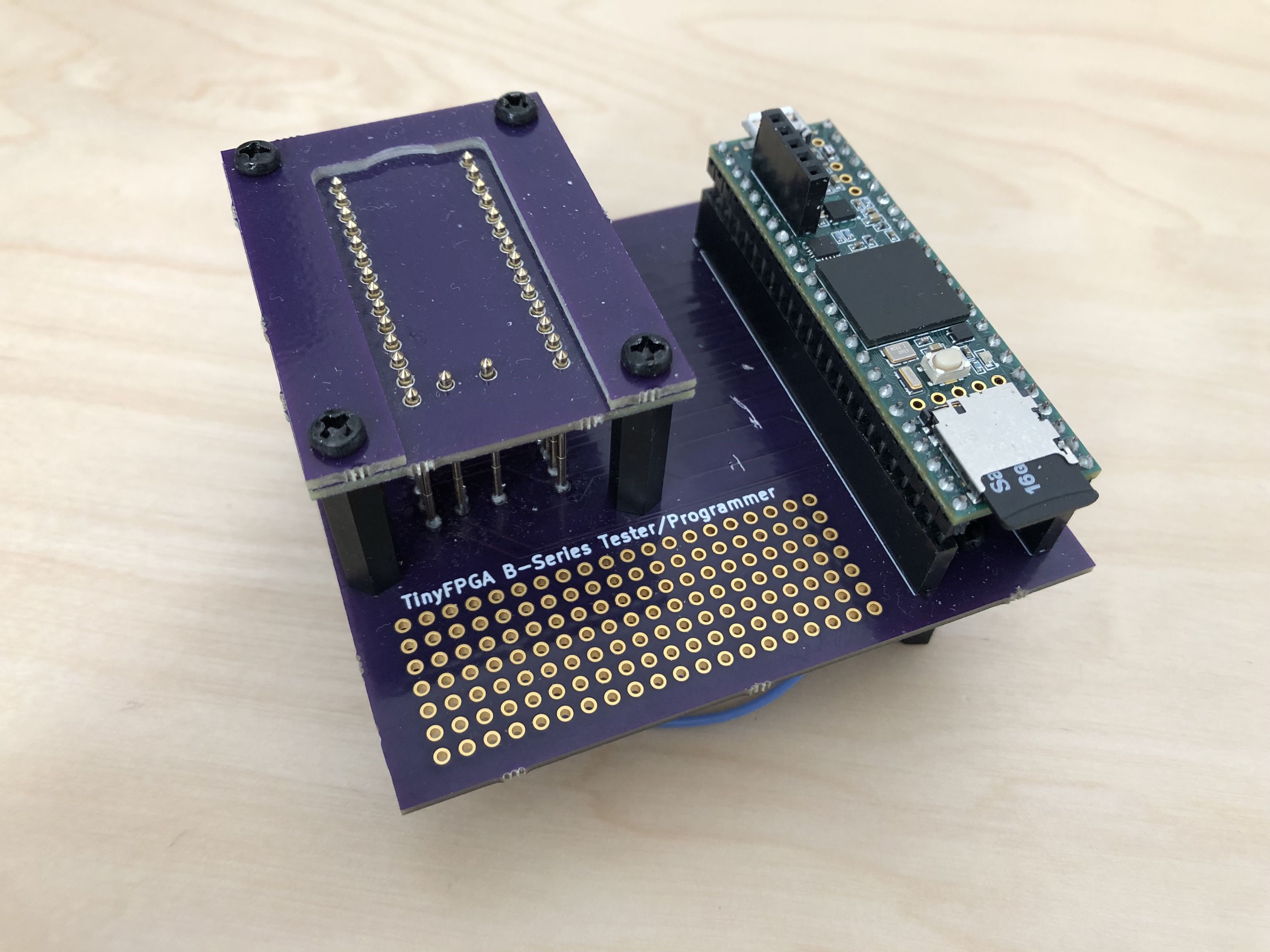
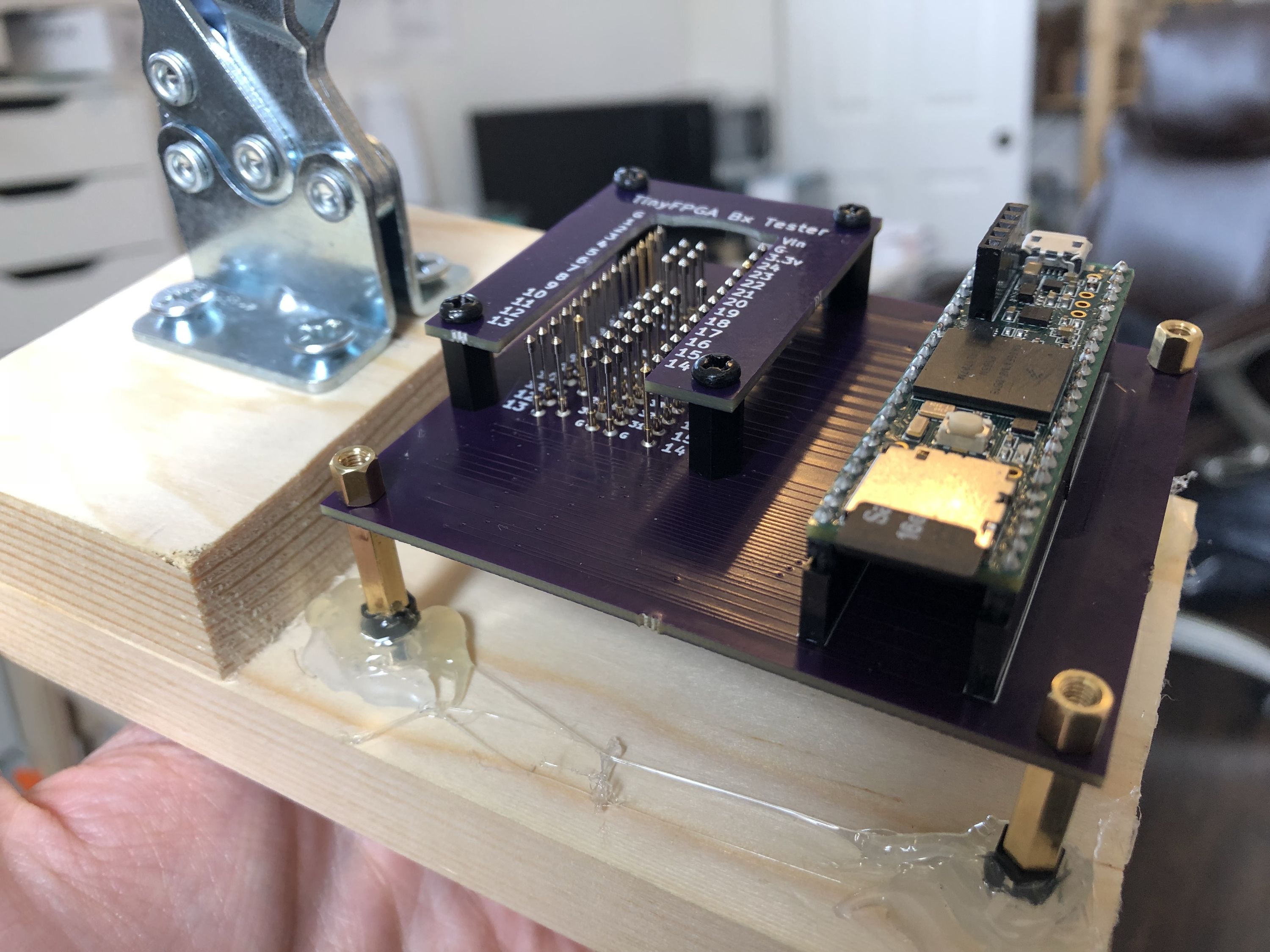
In order to simplify the test-jig design, I chose a Teensy 3.6 as the heart of the tester. The Teensy 3.6 supports many IO pins, is fast, self-contained, and has a micro SD card slot for storing the testing and bootloader firmware for the BX.
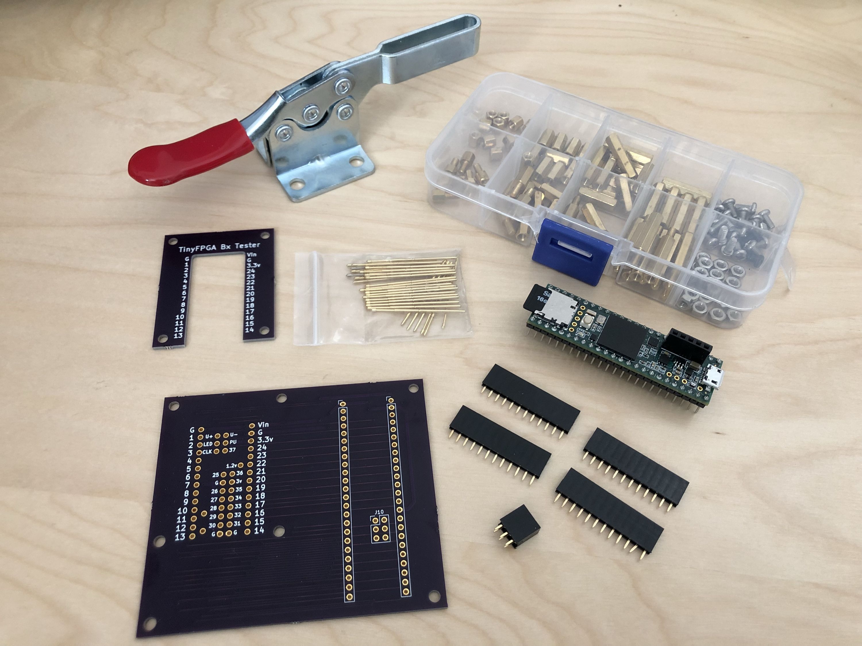
I then use standoffs to support the tester PCB over a wooden base, sockets for the Teensy, pogo-pins for making contact with the IOs, power, and test points of the BX, and a toggle-clamp to hold down the board under test.
The pogo-pins are spring-loaded pins that make electrical contact with the board under test. In order for the test-jig to operate reliably, all of the pogo-pins need to be straight and at the same height. To acheive this while soldering I created a jig with some extra stand-offs and PCBs to perfectly align the pogo-pins while soldering.
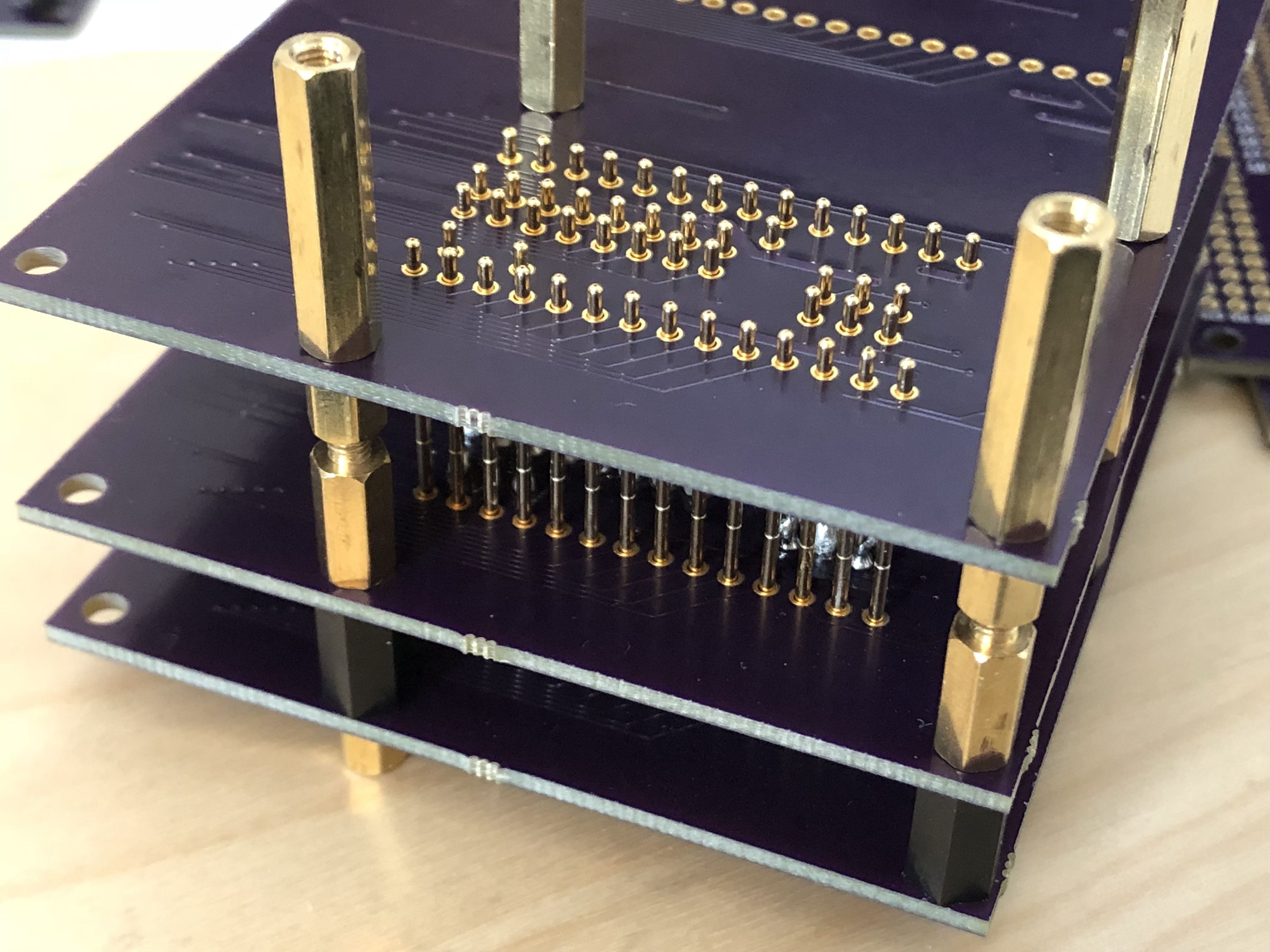
Once the pogo-pins were aligned in the jig I began carefully soldering them into place. The pins had to be soldered to the middle board in the alignement jig, so I had to insert the soldering iron tip between the boards to reach each location. This also means that the inner pins had to be soldered first, before the outer pins were inserted.
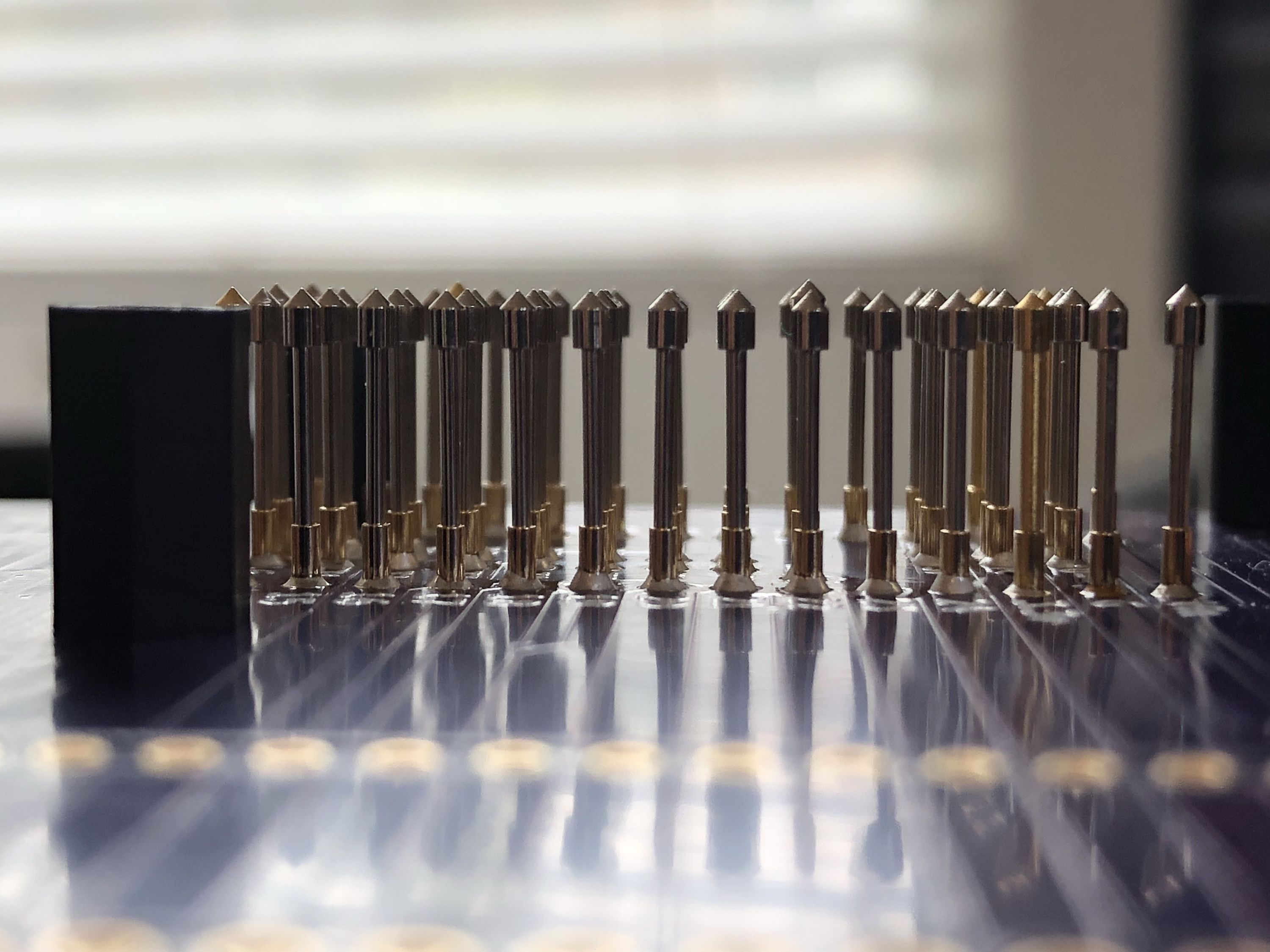
After the pins are soldered I checked the quality of the joints and alignment of the pins. The joints were all good, but a couple pins were a tiny fraction higher than others. This tiny deviation was acceptable. With the pogo-pins, Teensy sockets, and toggle-clamp installed, the test-jig is fully assembled.
Prototype Assembly
I had previously updated the tester firmware for the BX, but the final BX boards have a slightly different footprint than the assembled prototypes I had. In order to validate the new tester, I also needed to assemble a new PCB with the revised footprint.
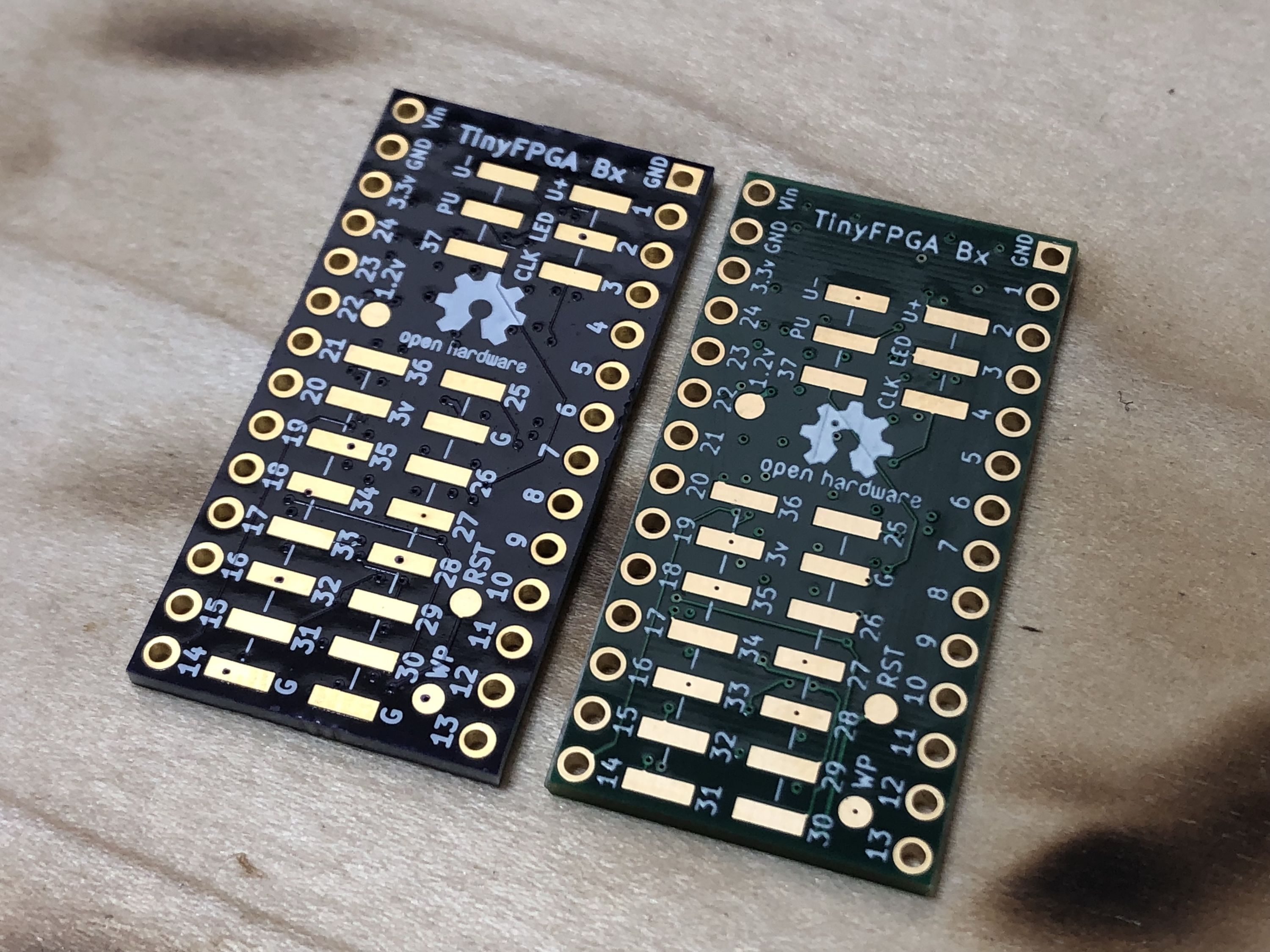
The new footprint adds additional ground connections essential for high-speed IO and shifts the surface mount header up 0.1 inches to become more compatible with the Teensy 3.2. Teensy 3.2 compatibility was always a goal of the BX, but I somehow committed an "off by one" error on the first PCBs.
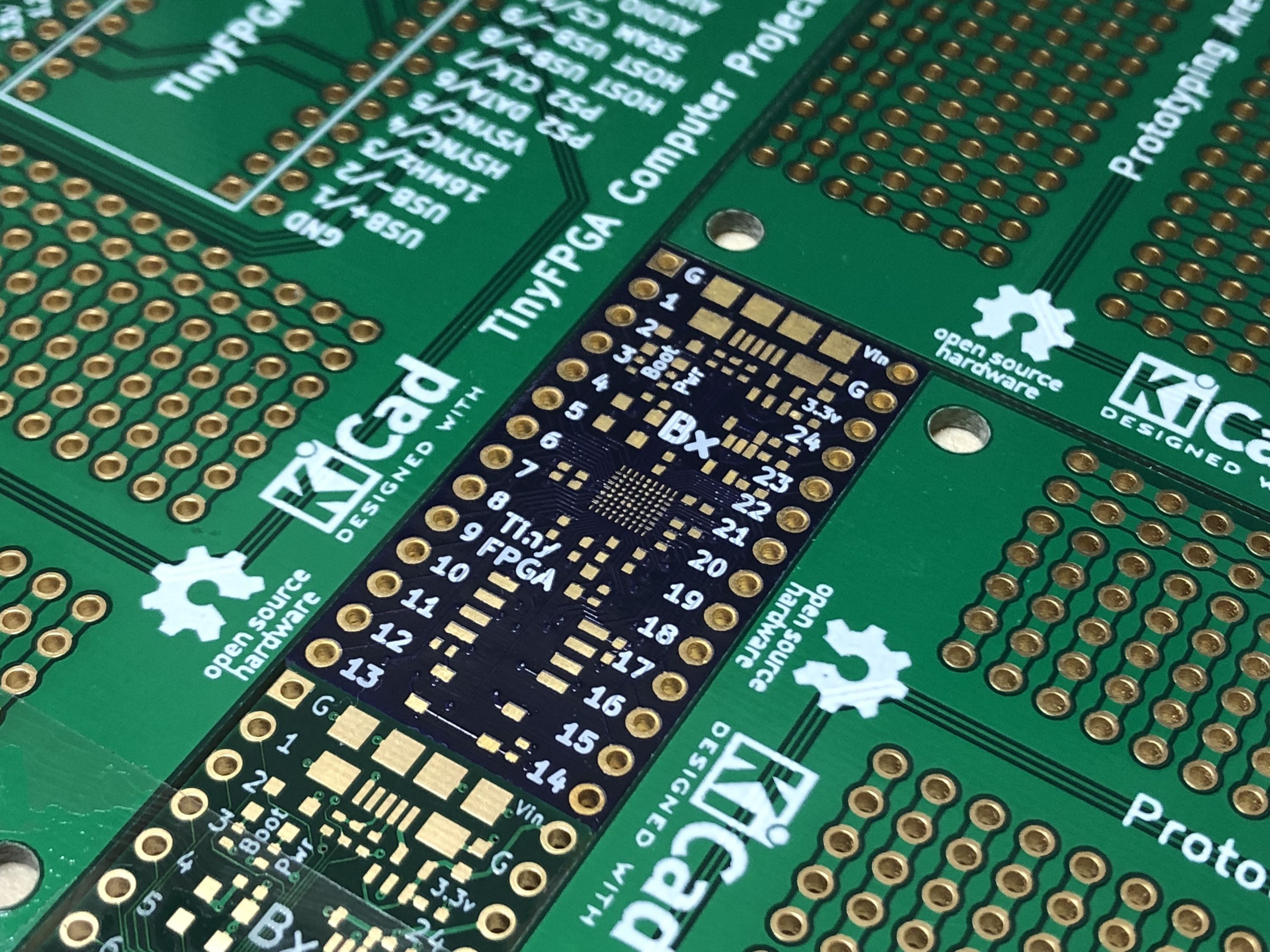
I already had a PCB prototype from OSH Park with the new footprint that I could assemble along with a stencil from OSH Stencils.
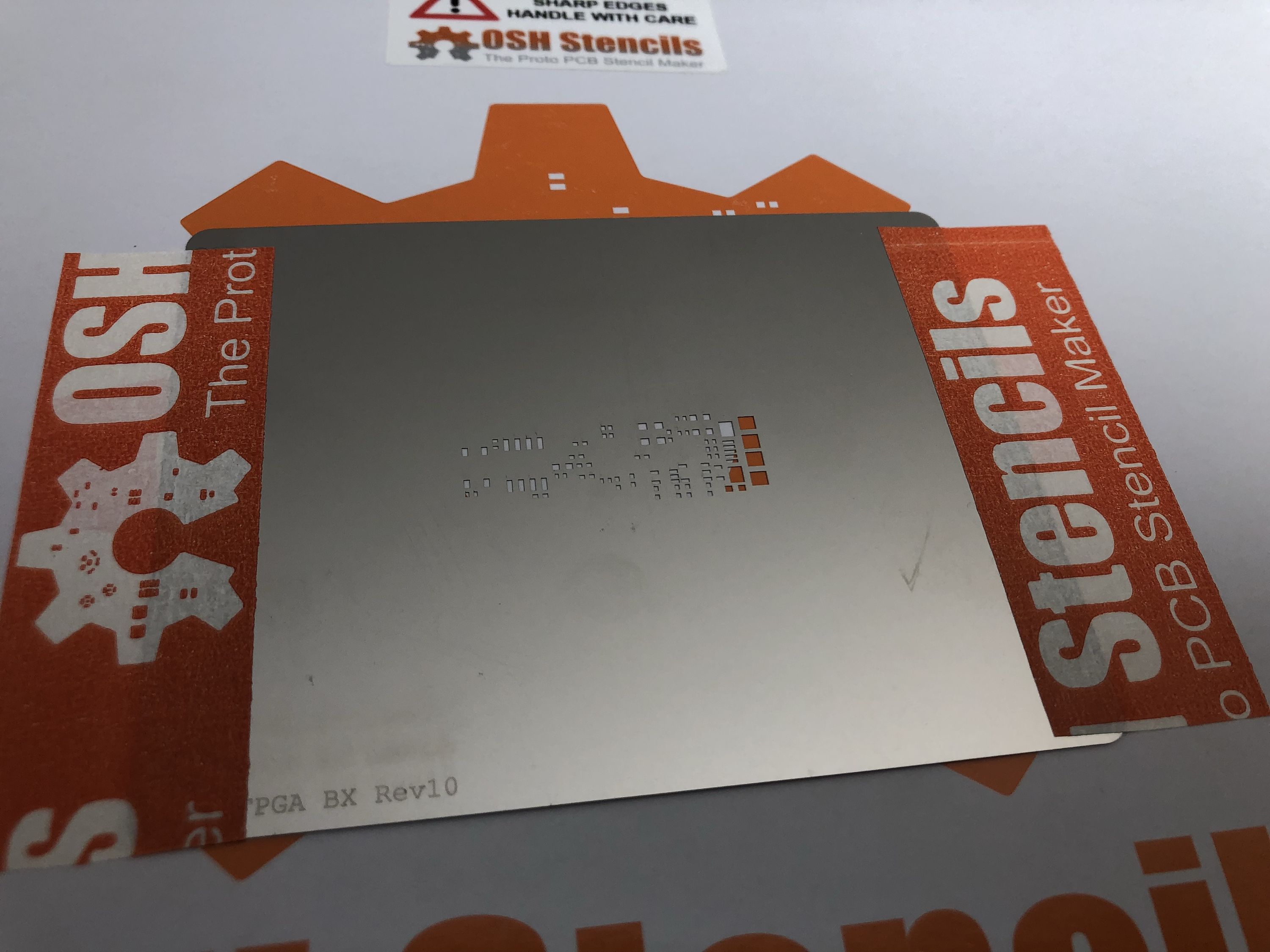
The stencil allows me to use a squeegee to "print" solder paste onto the pads for the surface mount components. I removed the holes for the FPGA package since I have found it is easier to use flux only for fine pitch BGA packages instead.
I had also previously ordered all the parts necessary for a few prototypes.
I used extra PCBs around the TinyFPGA BX prototype board to keep it in place while I apply the solder paste.
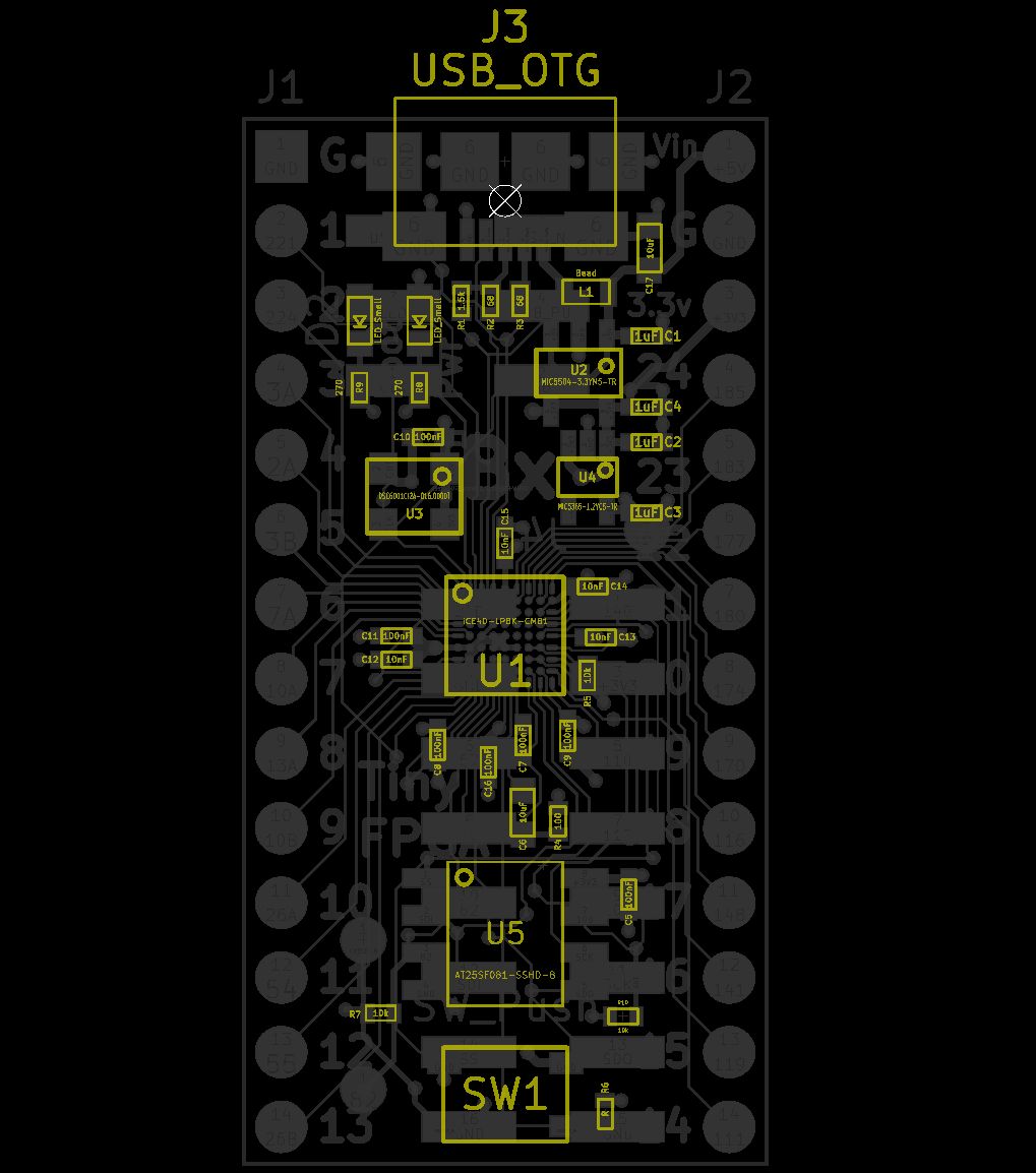
Once the solder paste is applied, I placed all the components with tweezers and a pair of magnifying glasses. I use the PCB layout as a reference for part orientation, location, and type.
I find that placing parts in order of size from smallest to largest works best. There are some cases where small components can be nestled between two large components and are very difficult to place otherwise.
The exact placement of the components is not critical as the solder paste will pull the components into the correct position during the reflow process.
I use a home-built reflow oven for prototypes. After the non-BGA components are reflowed, I use flux and a hot-air tool to reflow fine-pitch BGA packages. I have found that it is difficult to apply solder paste for fine-pitch BGAs and even more difficult to place the fine-pitch BGA on the paste. With flux, I can move the BGA around without worrying about smearing solder paste everywhere and risking shorts.
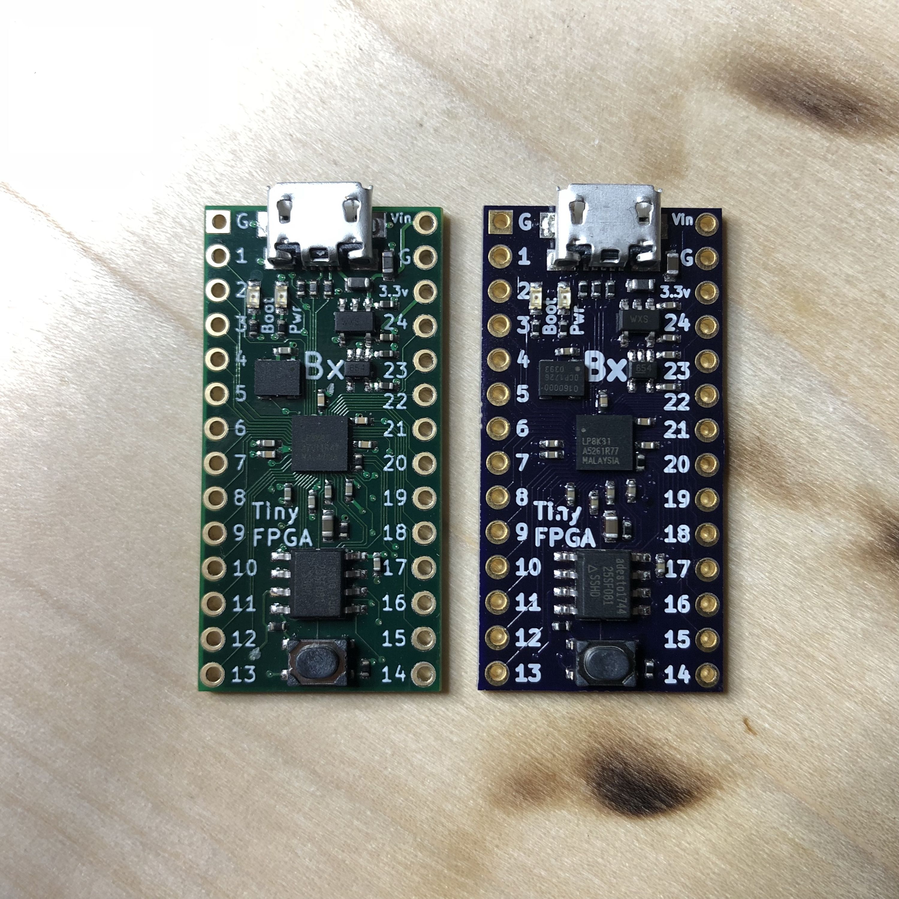
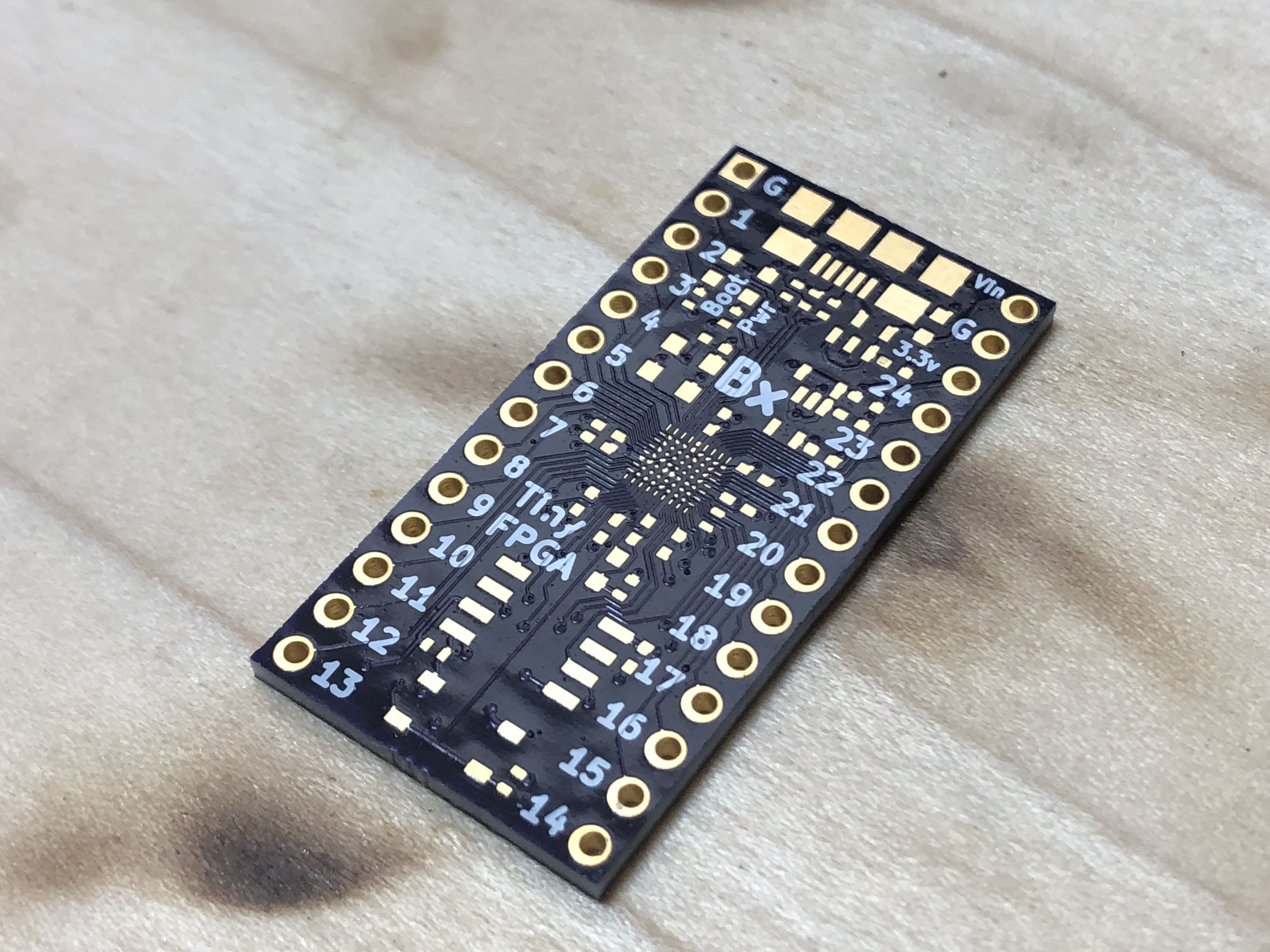
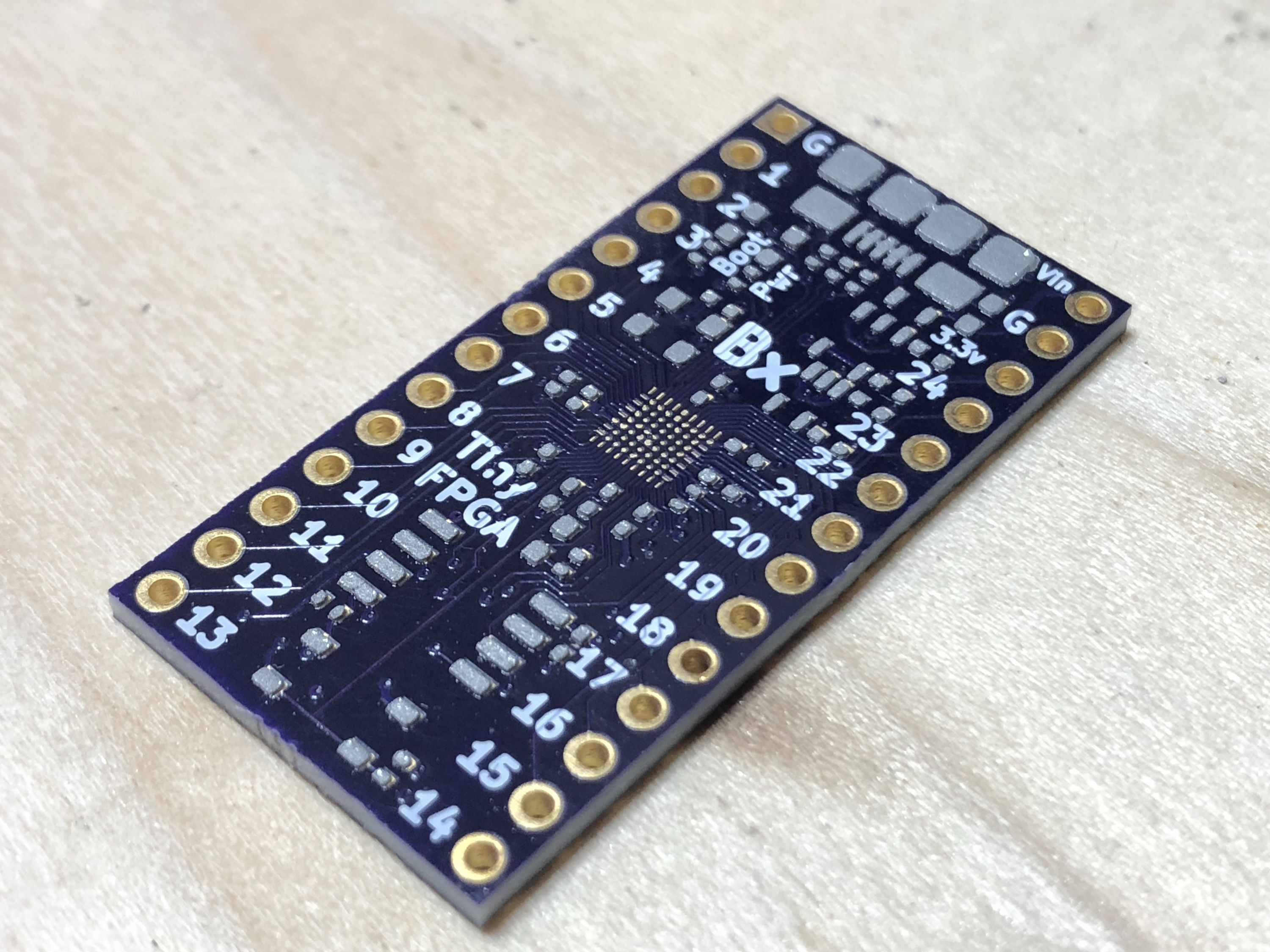
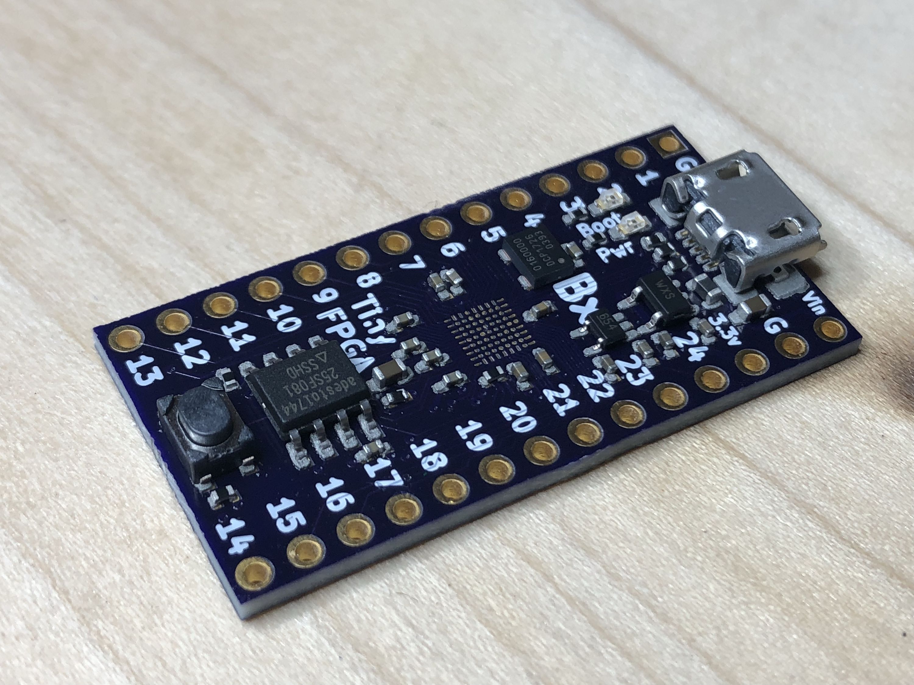
After the board is assembled I compared it to a prototype assembled from the factory, looks good!
Testing the Tester
But I still needed to run the board through the tester. Despite having a lot of success assembling prototypes with the teeny tiny iCE40LP8K-CM81 BGA package I am still nervous every single time I do it. I also needed to test the new tester.
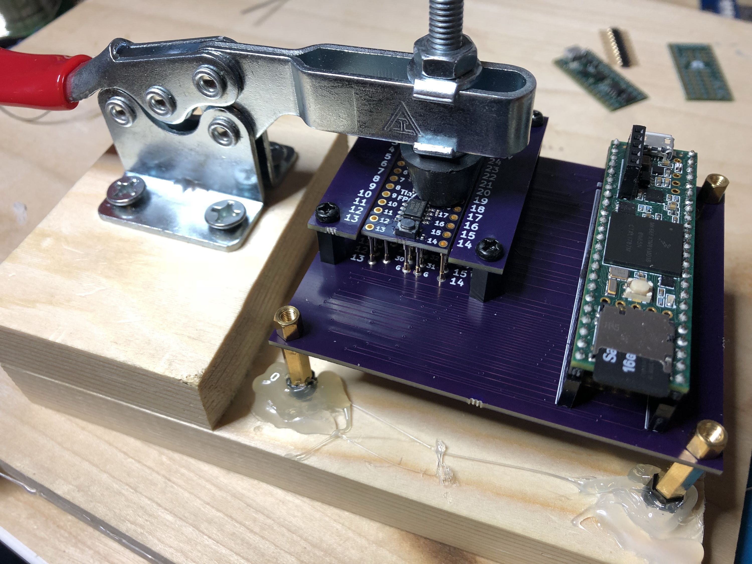
I placed the board into the test jig and waited for the results. I tried to make the test jig as easy to use as possible. There is no extra interaction with the jig required except for placing and removing the boards. No button to press. Instead the jig detects the 3.3 and 1.2 volts from the BX regulators and automatically initiates the testing and programming routine.
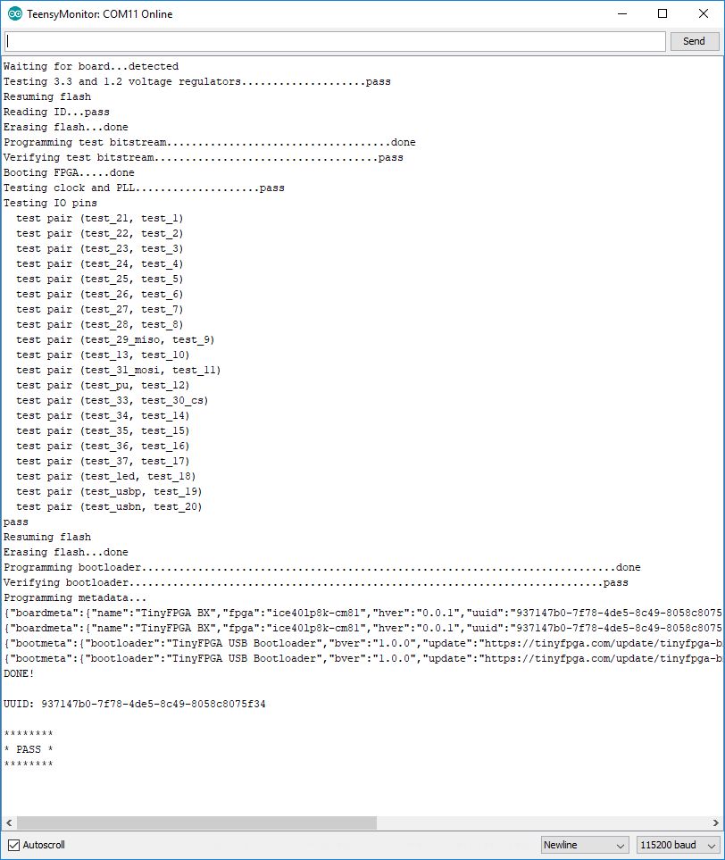
Success! The tester outputs status over the serial port which can be read with the Arduino serial monitor or any other serial terminal program. As it runs through the test and program procedure it communicates exactly what it is doing and if there are any errors. I was very happy to find that both the new prototype and the tester are both fully functional.
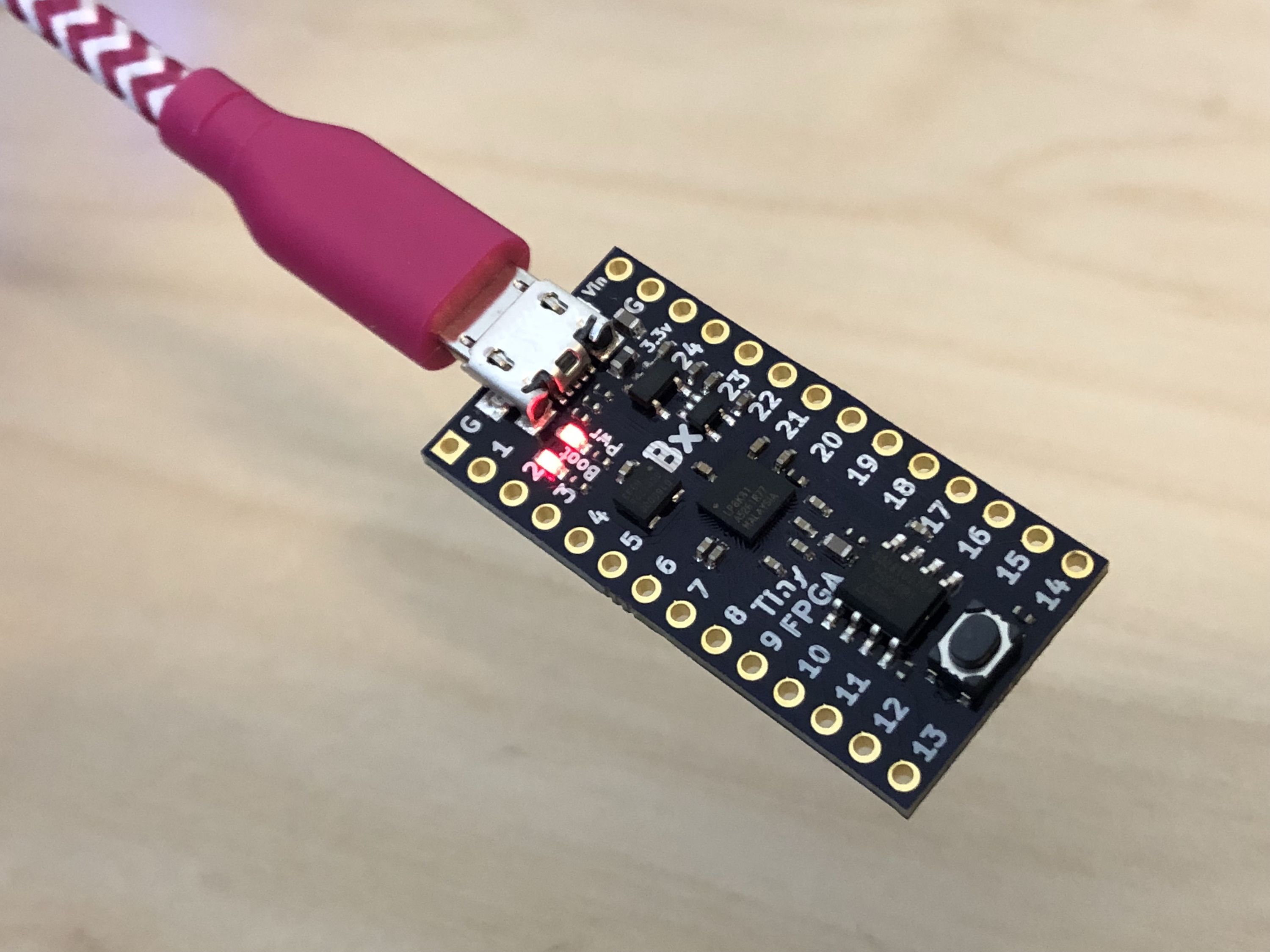
Plugging the board into a computer I immediately see the bootloader LED pulsate.
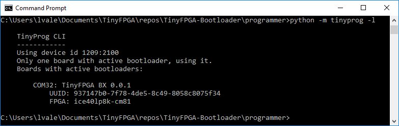
I used the tinyprog script to list connected boards and it appears as expected.
The new test jig was validated, but still too slow. It was taking about 60 seconds to program and test a board. The amount of support for this Crowd Supply campaign is incredible, I needed to make the tester faster. Going through the firmware I found several areas to improve:
- Overclock the Teensy 3.6 to 240 MHz
- Remove and reduce unnecessary delays
- Fetch data for next flash write while flash is writing previous data
- Instead of erasing the whole SPI flash chip, just erase what's necessary
With these improvements the complete testing and programming time is down to 12 seconds. This is fast enough to support the larger production run I’m expecting to order after the Crowd Supply campaign completes.
Thank You!
Again I want to thank you, a supporter of the project, for taking the time to catch up with the latest TinyFPGA BX news. You have helped to make this project a success and I think that’s just awesome. I’ll write you again next week!