Project update 13 of 15
Adding Hardware to CANFDuino for 12-24 V Power
by daniel kToday we are going to address an FAQ that has been asked a few times since launching the product: "is it possible to power CANFDuino off of 12 or 24 V power?". We have responded so far with: "Yes, using the prototyping space to add a regulator". This answer, while true, may not be so helpful. Here is a simple step-by-step guide that will walk you through the modification needed so you can power the CANFDuino off of 12-24 V without having to use the USB connection as the primary power source.
A voltage regulator is device that maintains a constant voltage level. It does this by adjusting the current flow in the circuit in response to changes in voltage, and in simple terms can be thought of as a "voltage converter". Voltage regulators can be either linear or switching devices, where switching devices are typically more efficient but may require more components, and linear devices are more simple but less efficient, as they require efficient heat dissipation when running under heavy load.
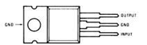
To keep things simple, we are going to use a linear regulator that will take our 12-24 V input and convert it into a stable 5 V power source for our CANFDuino. The part of choice for this modification will be the 7805 regulator which has been around forever, is very reliable, inexpensive, and comes in many packaging options.
Note: Please be aware that what follows is a modification that worked for us based upon the parts and setup we have here, your setup may not be exactly the same. Anytime you modify something, it comes with the risk of failure (including destroying the processor).
Step 1 – Design Circuit
The 7805 really only needs 1-2 components to go with it, at most. These are typically input and output capacitors that are used to smooth out any voltage ripple coming from the input side of the regulator, as well as damp any high frequency noise that could disrupt our semiconductors that will rely on this 5 V power rail.
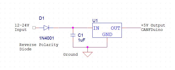
Above is a diagram showing the circuit we will add to the CANFDuino, which consists of the regulator, input capacitor and a blocking diode. The blocking diode is there to prevent reverse polarity from damaging the board, in layman’s terms this means switching the black and the red wires (which we have all done and so we always like to add this). We are omitting an output capacitor since the CANFDuino has this on the 5 V input side of the native 3.3 V regulator.
Step 2 – Buy & Build
This is pretty simple step, go to Mouser and add the components that seem to be the best package you are comfortable working with and will fit into your prototyping space. Since the CANFDuino supports SMT and through-hole components, and we had them laying around, we used a mix of through-hole and SMT for this circuit.
As you solder your parts on the CANFDuino, there is one critical step that we would encourage you to stop short of: do not solder the output of the regulator to the 5 V area of CANFDuino until you have built and tested the circuit. That is, build and test the circuit "in isolation" from the rest of the CANFDuino to prevent damage. When you are confident in your build, then make the final connection to the CANFDuino’s 5 V area (we advise this for all mods).
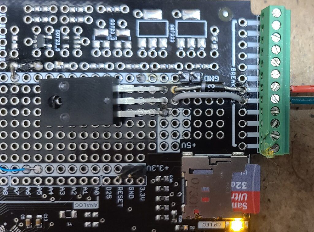
Above is a photo of our fully built mod (after tested and final output connected to 5 V). You can see we are using the breakout connections to the terminal blocks for ease of wiring to our 12-24 V input (red - positive input, green - negative input). Also note there is a tiny cap on the SMT pads that has wires run underneath, and we flipped the regulator for ease of wiring mounting and soldering which also flips the orientation of the input and output pins from the diagram.
Step 3 – Test Circuit
Once you have soldered all components in place, and made the power connections to the terminal block, it’s time to test. This is simple, connect your 12-24 V source to the terminal block wiring and then with a DMM check the output terminal pin, it should be at 5 V. If you have a good output of the regulator go ahead and now power down the circuit and solder the pin to the 5 V area. If you do not have 5 V, review your circuit design, pinout of the regulator and components, and check the integrity of your solder connections. Once corrected, try it all again until you succeed.
Step 4 – Wire and Power On
With the regulator output soldered to the 5 V area, remove the boot jumper if installed, turn the 12-24 V power back on. You should see the blinking of the orange GPLED as the bootloader is entered. From here, you are now able to have your CANFDuino permanently powered from the 12 V input while connecting USB whenever you like to program the unit or, sniff bus traffic. You can even combine this modification with our Bluetooth modification to leave the CANFDuino wired in to a vehicle and connect wirelessly!