Project update 6 of 10
Parallel Modular Entropy Multiplication and the USB Chip
Instead of using a programmable microcontroller, the Infinite Noise uses an USB FIFO chip in synchronous bit-bang mode to run the multiplier circuits and to transfer the random bits from the comparator outputs to you computer.
Only four of the eight available bits on the FIFO bus are used for this:
SWEN1andSWEN2are written by the driver to toggle two analog multiplexers at 240 kHz as clock signals for the modular entropy multipliers.COMP1andCOMP2are connected to the comparators outputs to receive samples from the capacitorsC8andC9
| Channel# | Connected to | Signal | Multiplier# |
|---|---|---|---|
| 1 | C8 | Analog | 1 |
| 2 | SWEN1 | Clock | 1 |
| 3 | C9 | Analog | 2 |
| 4 | SWEN2 | Inverted clock | 2 |
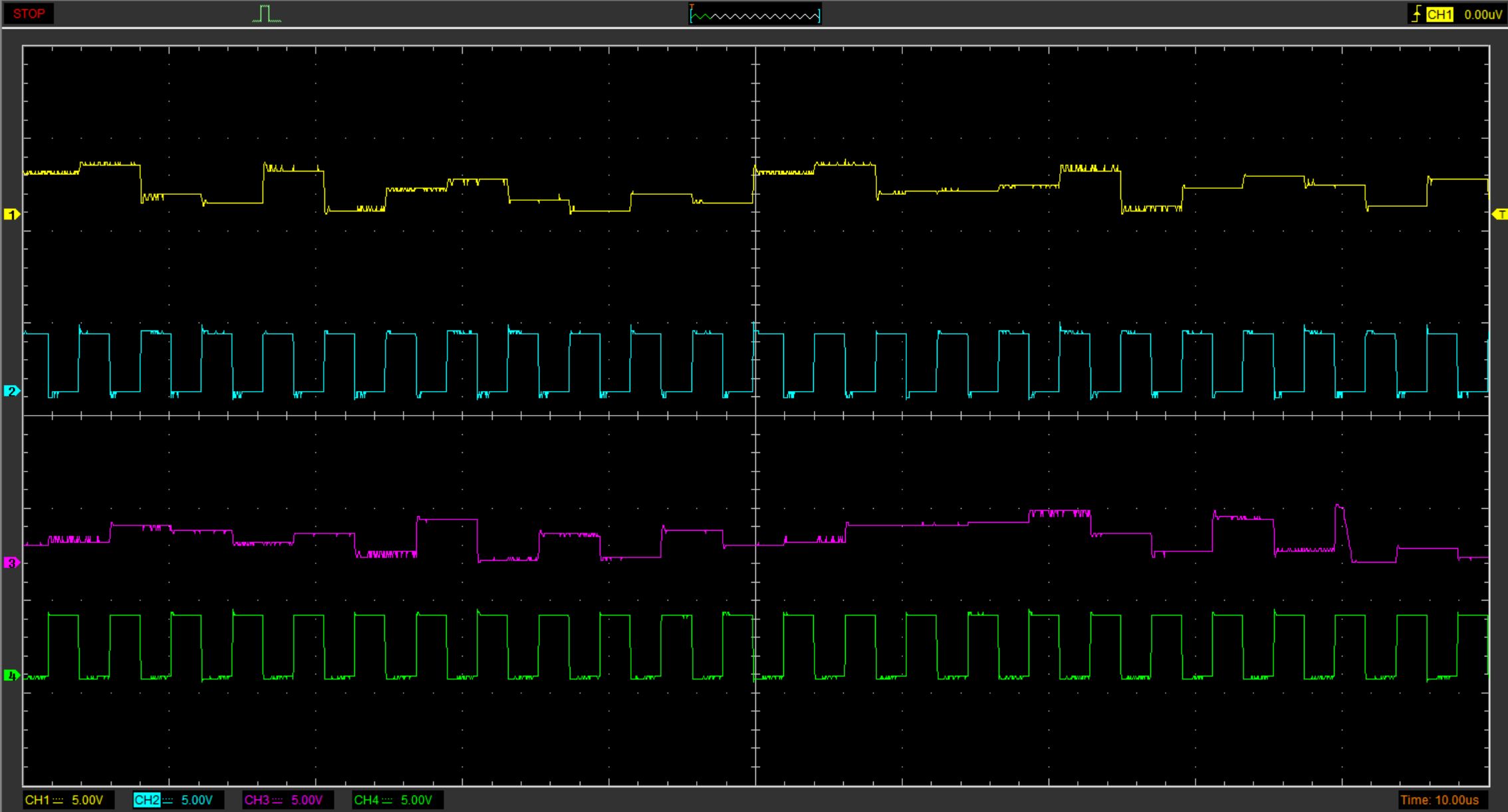
As you can see in the above plot, the analog output only changes with the rising edge of the clock, as both entropy multipliers are controlled with an inverted clock signal.
Each multiplier performs the multiplication (described in the section "how it works" on the campaign page) on its respective high-cycle, and thus the digital output will only change every second toggle.
That’s why we need to take alternating samples from the digital outputs synchronously to the clock signals.
Output via USB
Initially I wanted to show how the signal of both multipliers looks in a combined form, but there is a lot of overhead added by the USB protocol and the way the USB chip is being used.
It’s very inefficient indeed, as we need to write one byte to toggle the switches and read one byte to extract a single bit of entropy from one digital output. Then repeat and read from the other output.
This gives us two bits of entropy while 32 bits of data are actually transferred over the bus (not to mention the USB protocol overhead).
As is runs in synchronous bit-bang mode, the drivers just writes the output buffer to toggle the switches and then reads the full input buffer to extract our entropy, which is only 64 bytes of the 512 byte buffer. It also checks if the whole in-/output operation was completed within the expected time (5ms), just to make sure the chip performed as expected.
| Channel# | Connected to | Signal | Multiplier# |
|---|---|---|---|
| 1 | USB | D+ | both |
| 2 | COMP1 | Digital | 1 |
| 3 | COMP2 | Digital | 2 |
Initially I wanted to show how the USB parts works on the scope, and tried - but it needs a lot more processing (and probably much longer samples) to decode the USB signal. You can grab captured data if you wanna give it a try: (1µs/division: image/data, 500ns/division: data)
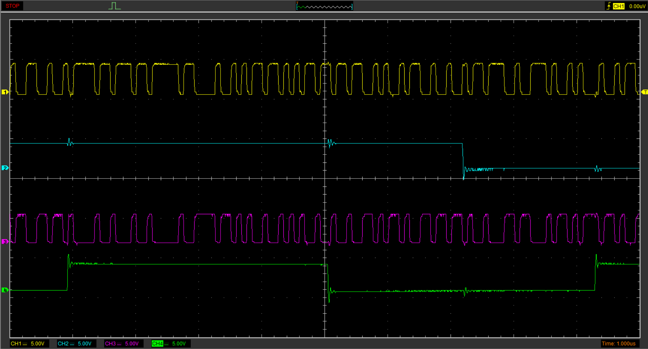
Fortunately analyzing this is not neccesary at all - as you can actually read how its done in the driver’s source code.
If you want to do so, check the method extractBytes() and the while loop starting from // Endless loop: set SW1EN and SW2EN alternately in infnoise.c. (note this method has moved to libinfnoise.c in the current development version)
Why so complicated?
A microcontroller could manage this a lot more efficient, but they have the big downside of being programmable.
The off-the-shelf USB FIFO chip FT240 can accomplish this complex time-critical task without any firmware on the device itself - and it should be completely hardwired as the datasheet states:
Entire USB protocol handled on the chip. No USB specific firmware programming required.
Its little sister, the very popular FT232 UART chip has the same statement in its datasheet and has been decapped long ago, confirming this for genuine FT232 chips. But also shows there could be some (re-)programmable logic under the hood instead. At least the cheap clones of the FT232 use a generic mask-programmable microcontroller design. Presuming they’ve put the correct firmware onto it (as silicon layer) doing only what it should, this wouldn’t even be a problem for your security.
Although it is very unlikely that fake chips of the FT240 exist as it’s not as popular as the FT232, I get (almost) all the parts from Digi-Key.
For even more confidence, and to make the Infinite Noise TRNG the most transparent and secure random number generator, I started decapping some FT240 chips to see what’s going on in there:
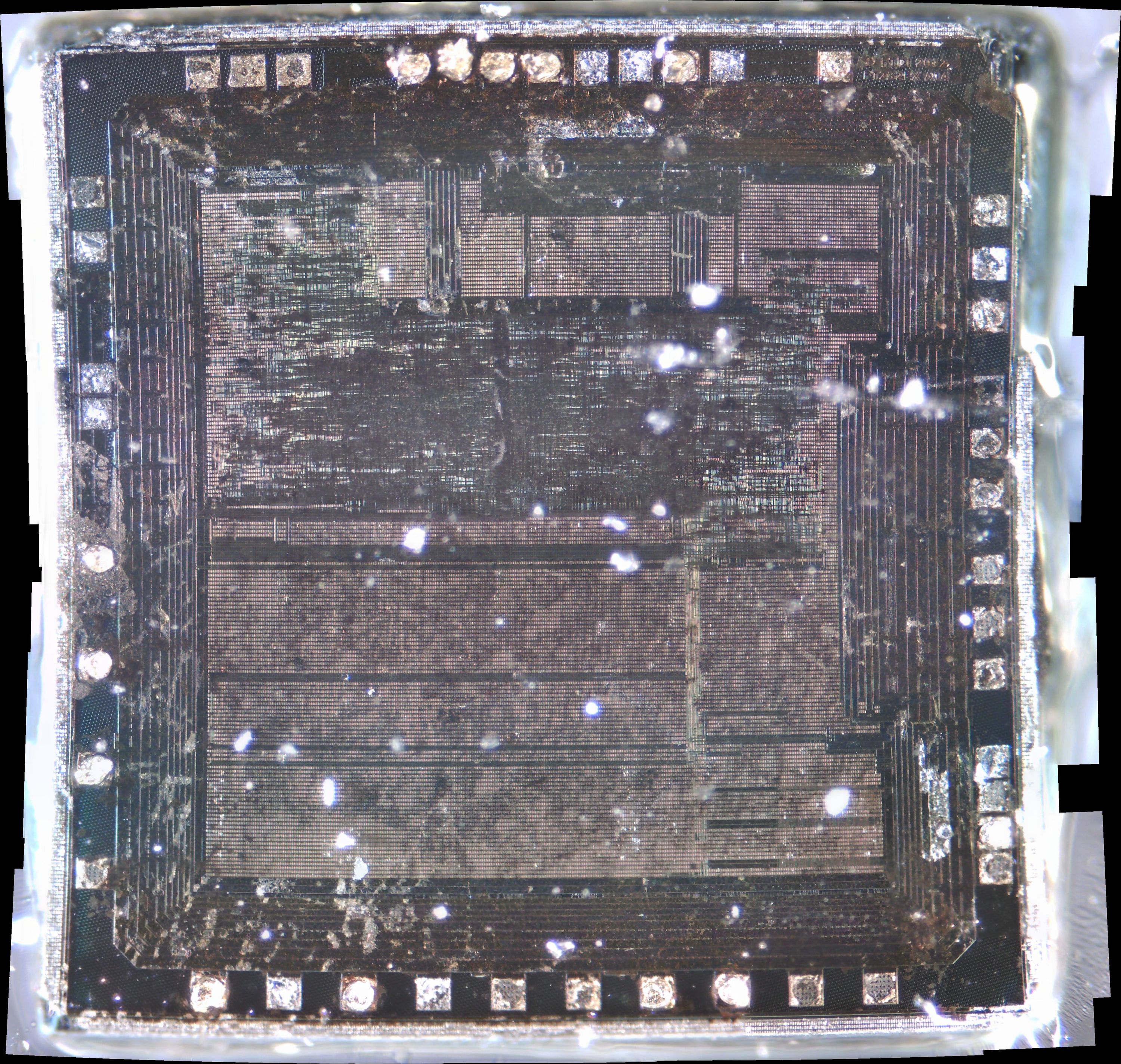
It’s a long road to go down - even if the goal is just some micrometers away. Still only the first metal-layer, but now you can actually see something - and more importantly: I can take the next step and start delayering. The die is about 3x3mm in size, so at 10x magnification, I had to make 100 images and stitch ‘em together to get the full picture.
With my old cheap USB microscope I wasn’t even able to evaluate if its worth sending a sample for professional scanning. With some more tweaking, I may now be able do it by myself.
There is already a pretty strange finding: When you take very close look at the upper right corner you may eventually recognize the marking on the chip:
FT232EX A14 Seriously, I have no idea why its labeled like this. Maybe its worth finding some FT232 chips from 2012…
Let’s see what the next chip brings up!