Project update 11 of 14
Plastics and Production
Greetings, and happy holidays!
I’m writing this update from Incheon airport, on my way back from a successful experience at the NeTV2 production facility. First I’ll elaborate on the process of designing and making plastic cases, and then I’ll summarize the overall status of production.
The Design and Manufacture of Plastic Cases
Over the years, I’ve had to learn how to design plastic cases as a survival skill. Almost every product that isn’t a development board involves some injection molded plastic parts; as a result, understanding the design and implementation of plastics is an important skill for anyone looking to produce consumer-ready electronics.
There are basically two schools of thought for the design of plastic cases: parametric, and free-form. Parametric design strives to describe an object entirely based on mathematical relationships. Free-form design gives the designer a digital lump of clay that is sculpted using free-form tools.
Free-form Design
Clearly, free-form design is more intuitive, and it’s easier to do stunning, emotive and sleek designs. However, it’s also harder to move free-form designs into production: it’s difficult to translate a free-form design into tooling paths; simple operations like scaling a free-form design can lead to counter-intuitive results; and getting all the mounting holes and port locations correct in relation to the arbitrary shape of the case can be tricky. Scaling a design is necessary for operations like "shelling": plastics aren’t molded as a solid block; they are hollow. The outer free-form cosmetic surface thus needs to be computationally converted into a shell by scaling the outer surface inwards. Plastics also shrink sligthly after molding, and so a design has to be scaled accordingly so the final plastic piece has accurate dimensions.
Parametric Design
To simplify mold design and the incorporation of internal mounting features, I prefer to use the parametric design flow. It’s initially frustrating to learn how to describe everything using mathematical relationships, but once you get the hang of breaking a complicated design into parametric primitives, the design process becomes snappy. As a bonus, you can easily create variations by tweaking parameters, exploring how the case might look if it were longer or fatter. A well-constrained parametric model will automatically propagate the tweaks and generate a new case design — with correct mounting locations for internal hardware, shelling, and all. This is really helpful, especially when you get your first 3D prints back and realize you need to add a few millimeters here or there to make everything fit together nicely.
The popularity of the parametric design flow explains why lots of plastic goods assume fairly simple geometric shapes — it’s difficult to describe organic-looking curves parametrically. Of course, Solidworks offers features like splines, which I use to describe the peanut-shaped outer contours of the case, but even then my case design still has an admittedly simplistic look and feel to it.
If you’re curious and want to dig into the details of the case design, you can check out the plastic case git repository and poke around the design using a STEP file viewer.
Creating the Injection Mold
Of course, once the net shape of a case is designed, it has to be turned into an injection molding tool. This requires inverting the shape (subtracting the volume of the plastic from the steel, leaving a cavity into which plastic flows), picking a "parting line" (the line along which the two halves of the molding tool come apart), and surrounding it with features like "ejector pins" (to force the plastic out of the tool), "sliders" (moving parts to make through-holes or undercut features), and "gates" (points where plastic enters the mold). A number of small adjustments are made to non-cosmetic surfaces to improve the flow of plastic within the tool, and to prevent problems with warpage or the part getting stuck in the tool. Once this is done, the whole assembly gets milled out of steel using a combination of traditional CNC, EDM (electron discharge machining, not electronic dance music), and good old hand polishing in a process that takes about a month.
Initial Injection Mold Results
The very first trial of injection molding a plastic part is typically called the "T0" shot. Although mold designers perform detailed numerical simulations to optimize the flow and pressure of plastic in the tool, the complexity of nature still defies our best attempts to reduce it to ones and zeroes. In the case of NeTV2, the T0 shot had difficulties with the hole pattern on the top of the case.
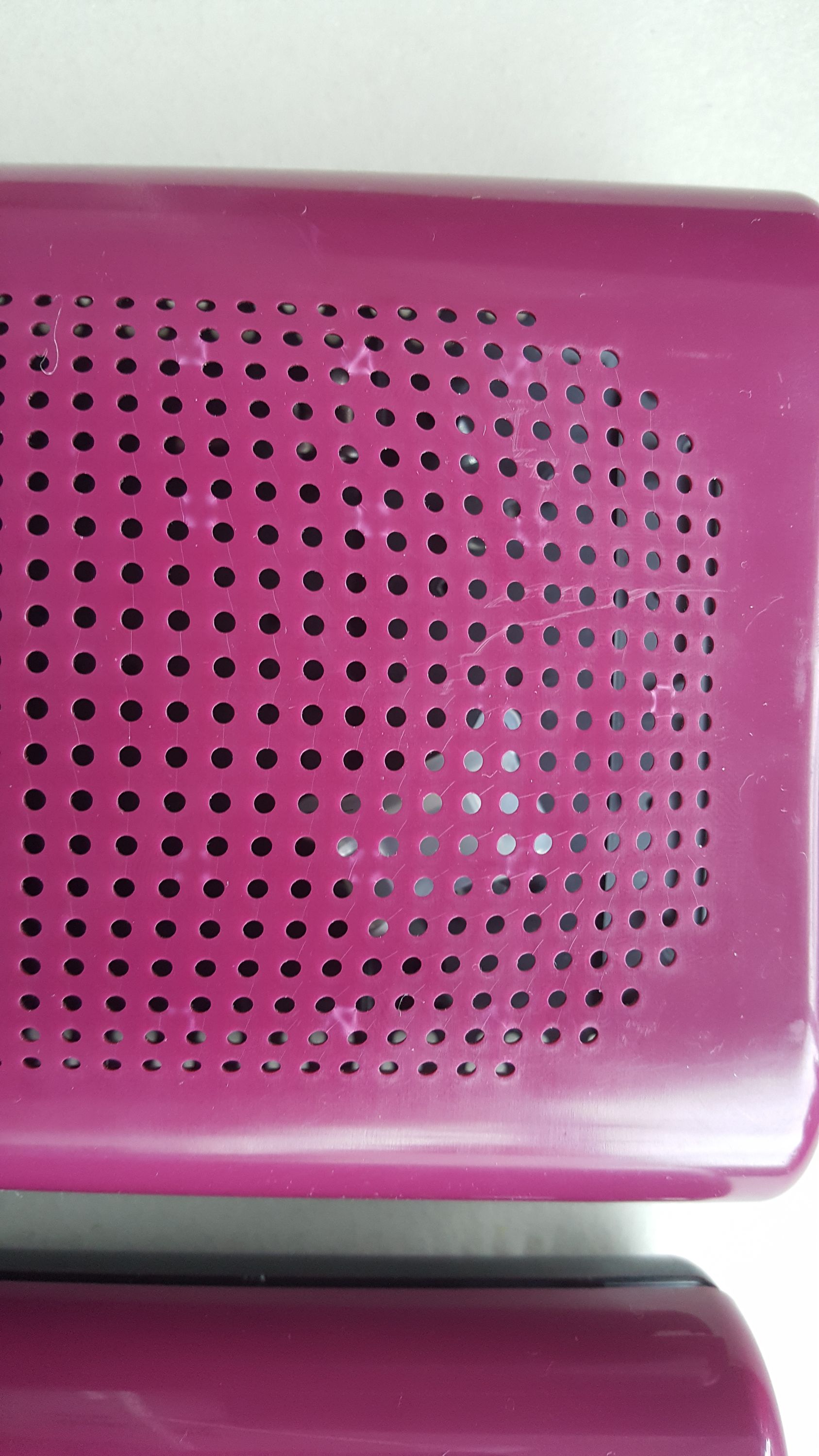
Above is a detail shot of one of the problem areas of the case. You will notice two types of defects: white patches and tiny cracks. The white patches are caused by the stress of the ejector pins pushing the plastic out of the mold. The tiny cracks are called "knit lines," and are caused when plastic flows around the steel pegs that define the holes in the case and meet on the other side. Knit lines are actually very hard to entirely get rid of. Typically, the best you can do is minimize their size, especially with a mirror finish like the one used on the NeTV2 case. This is why many consumer electronic products use a satin finish, as such a texture will hide microscopic artifacts like knit lines.
Once problems like this are identified, the tool is modified. For example, extra ejector pins may have been added to reduce the ejection force on each of the pins, thus eliminating stress marks. Then the plastic is shot again, and re-evaluated for cosmetic quality.
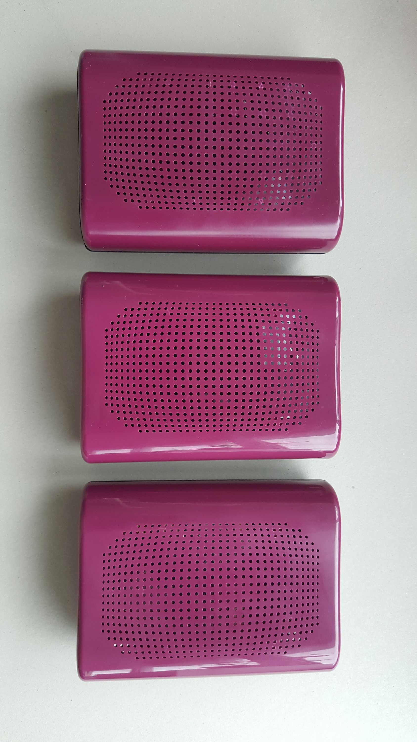
Altogether, the NeTV2 tool went through two rounds of modifications and then a finishing stage where it is polished to a mirror finish (or textured as required). Below is a photo of the three generations of NeTV2 plastics, from T0 on the left to T2 on the right.
Production
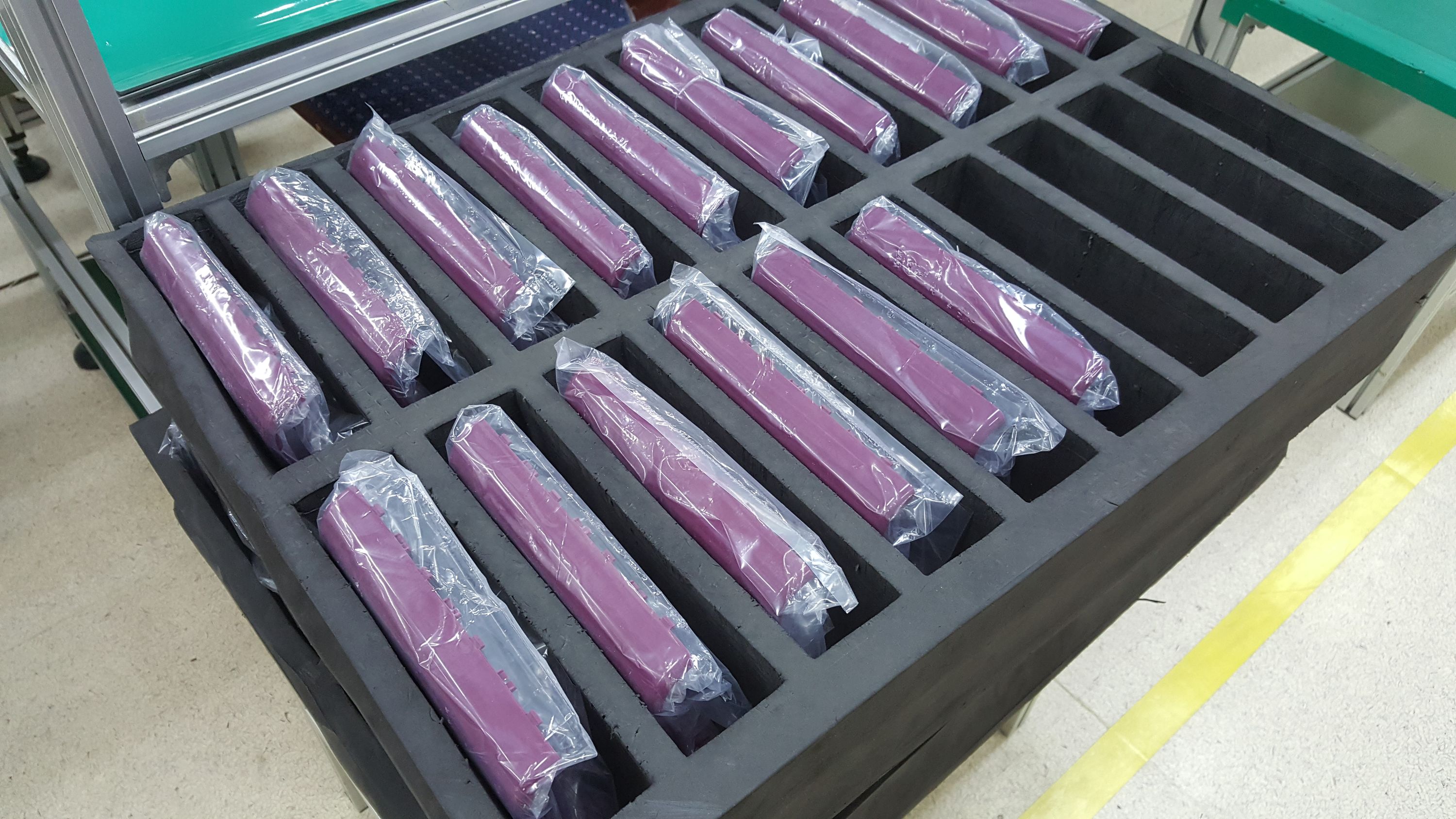
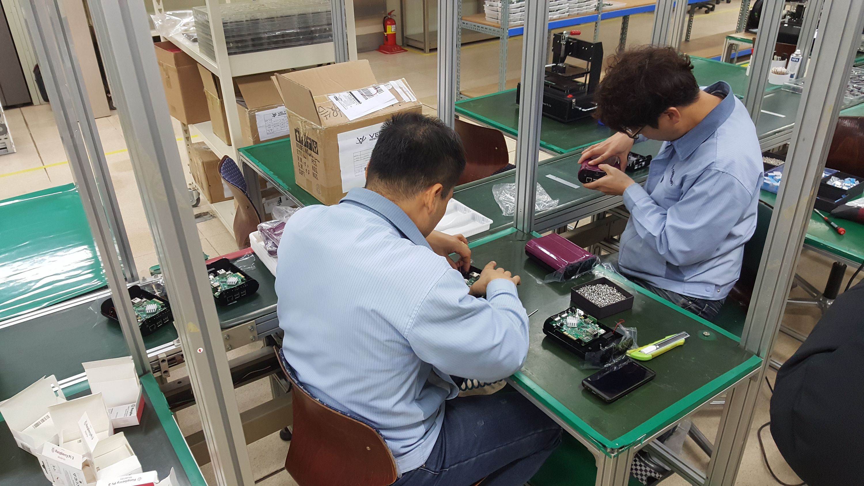
Thus refined and approved for production, we took some of the T2 plastic samples to Korea to attempt our first full-product test build on the assembly line. So, my second visit to the factory was spent working through the operating procedures for assembly, final inspection, and packaging of the full product. While this can be done remotely, I find it much more expedient and cost-neutral to be on the factory floor; it only takes a few rounds of FedExing samples before you’ve spent on courier fees alone the cost of an economy flight from Singapore to Korea. Also, each round of FedExed samples takes a few days to make its journey, making it time-prohibitive to iterate on all the small details that would otherwise impact product quality.
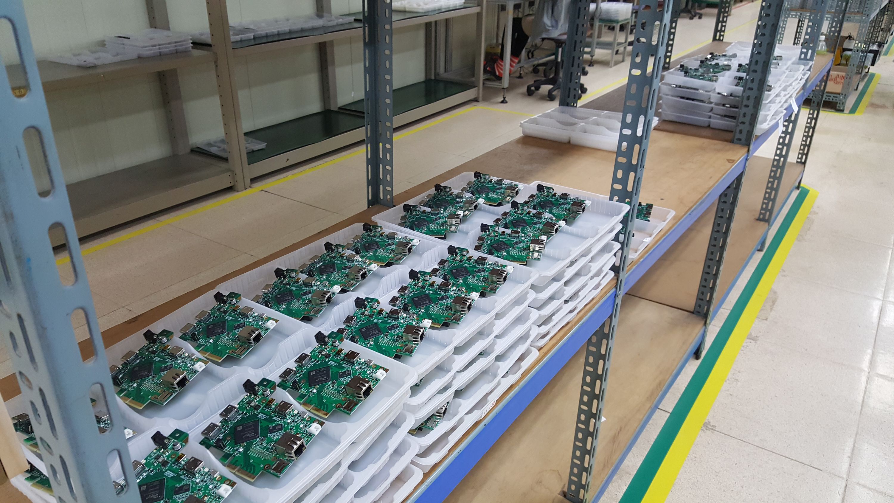
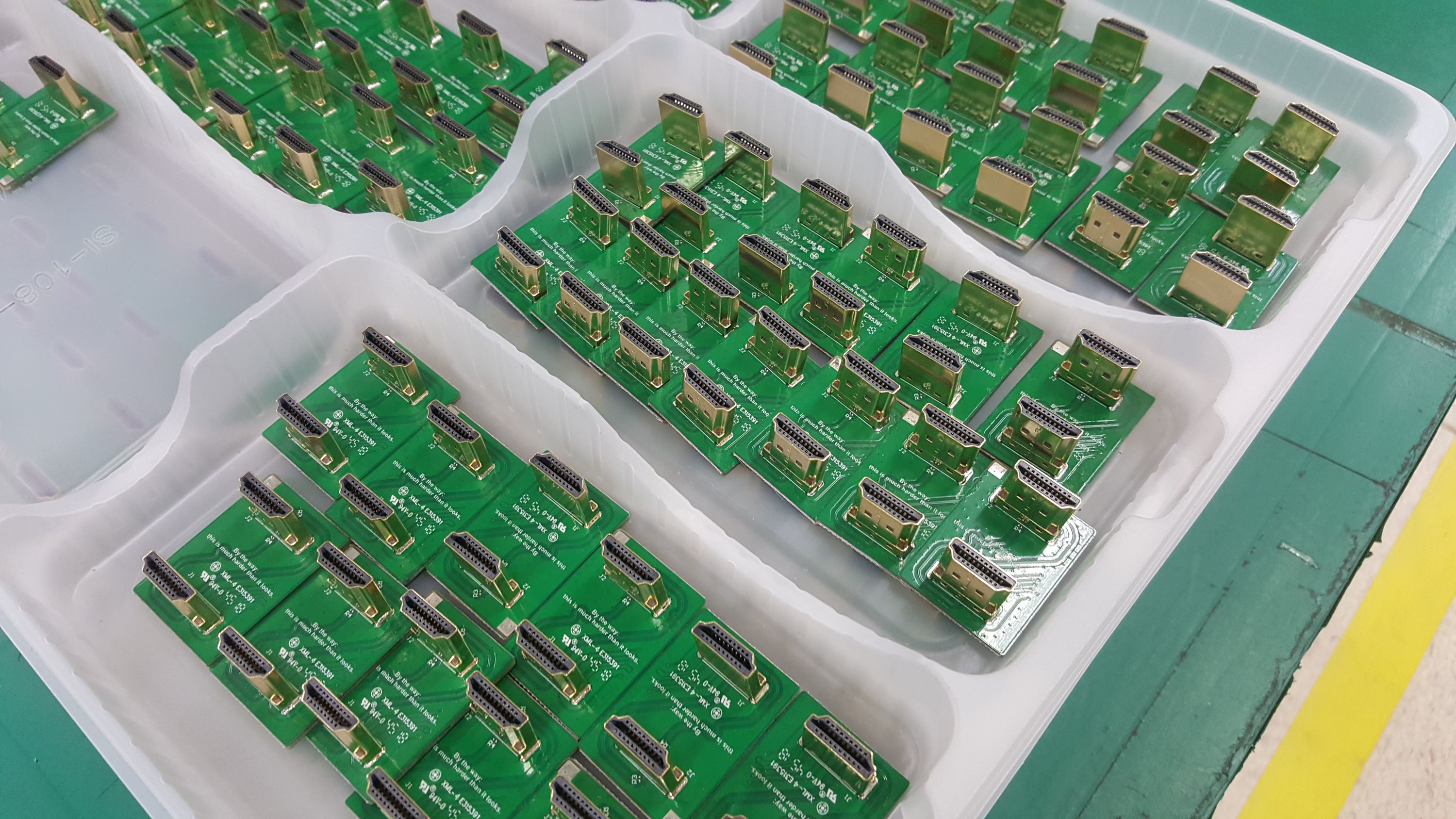
By this time, all the NeTV2 main boards were built and tested, as well as the accessory boards. Every NeTV2 main board goes through a comprehensive three-stage test program, where the first two stages are run using an open source hardware testing infrastructure developed by Sean ‘Xobs’ Cross called "Exclave". I recently wrote a comprehensive blog post about the challenge of production testing hardware, check it out if you want to learn more about this facet of hardware production.
In the course of an afternoon, we were able to crank out the first few fully assembled units and work through a couple minor snags in the final test and firmware updating procedure.
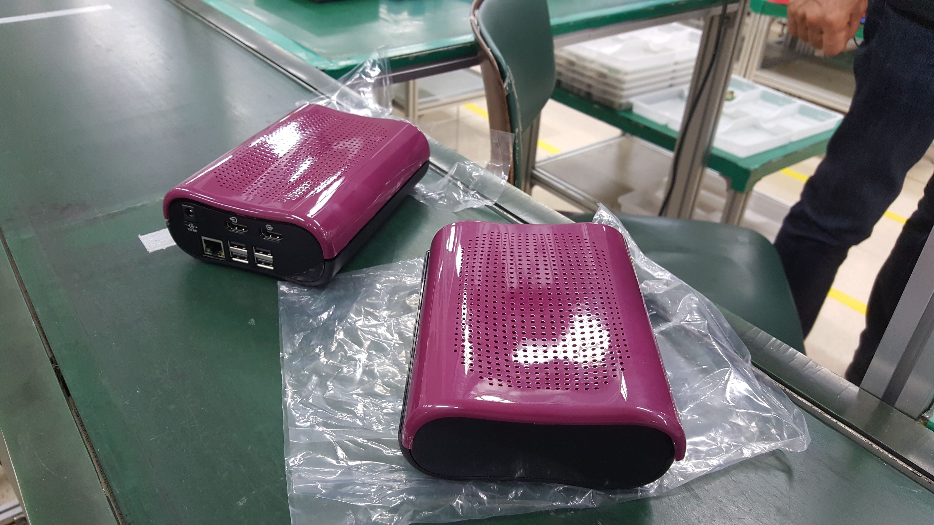
I’m pleased with the quality of the first samples, and have instructed the factory to proceed with the production of all the units promised to backers of this campaign.
Production will probably conclude in a couple of weeks, which just nicely coincides with the timing of our FCC and CE paperwork finally being issued, clearing the way for the legal importation of the product to the US and EU.
By the way, getting FCC and CE clearance for NeTV2 was really hard for entirely non-technical reasons. I had opted to use the Raspberry Pi 3B+ in the NeTV2 because it’s certified for use as a radio module. The good news is that the 3B+ was whisper-quiet and contributed almost nothing to the unintentional radiated noise budget; so technically, we passed with flying colors. The bad news is that legal language on the actual radio module certificates for the 3B+ made it unlawful for me to reproduce the certificate for any purpose, such as forwarding a copy of the certificates to regulators to inspect and verify. The exact text read "This test report shall not be reproduced in full or partial, without the written approval of UL VS LTD."
The certification shop I was using for my product insisted that I produce such a written approval, otherwise they could not issue the paperwork for my product. The other option, of course, would be to fork over a pile of cash and do the expensive and time consuming full radio transmitter certification with them, which I’m sure was partially their motivation for being such rule-sticklers. However, I did run the language past some legal experts and they agreed that in fact their interpretation of the situtation was correct and not entirely unreasonable.
Unfortunately, UL VS LTD was loathe to issue such approval, stating that "strict protection requirements must be adhered to," due to "explicit rules" in ISO 17025 for "the protection and integrity of test results and test reports." I’ll spare you recounting the details of the two-month-long saga of securing the authorization letter, but suffice to say we had to work through three revisions of the letter, involve multiple lawyers, and ultimately escalate to the Raspberry Pi CEO to get it resolved.
The final revision of the letter was very narrowly drafted, so it’s only good for supporting the certification of the NeTV2. This means anyone else who cares to respect copyright law will also have to jump through the same hoops to secure a letter of authorization. However, in practice, it seems I’m the first and only person to care about respecting the anti-reproduction provision: such a letter of authorization had never been requested before, which is why it took so many lawyers and so many iterations to get right. Of course, one way to avoid all of this might be to use UL VS LTD to certify the entire product, but given my tight budget and geographic location, it just didn’t make sense to engage a UK-based lab to test the NeTV2. My mistake was naively assuming that competing testing houses would have any incentive to play nice, work together and get the job done.
Getting these certificates sorted out was by far the most aggravating and stressful aspect of pushing NeTV2 across the finish line to date. I maintain that these regulatory burdens are too heavy and they discourage innovation; there are many fun projects on a scale smaller than NeTV2 that I have wanted to share with a broader group of people, but the regulatory burden has deterred me from offerring these projects to the general public.
Receiving and Using Your NeTV2
After production, your NeTV2 has to make the long trip from Korea to Crowd Supply’s warehouse in Portland, Oregon, USA, and then to your doorstep. This journey takes a while: about 3-4 weeks to cross the Pacific Ocean, and then a couple weeks to pick, pack, and transport to your front door, depending upon where that might be in the world. The good news is despite that, we’re still on track to deliver your pledges ahead of our May 2019 promise, barring any unforseen complications or further escalations of the trade war.
To help you get started using your NeTV2 unit, I’ve prepared a GitHub wiki with the documentation you’ll need. I’ve also opened up an NeTV2 subreddit for discussion about the product and/or non-technical support. Please go easy on me; I’m the only person working to support the product, and I’m also new to Reddit, so I don’t know all the conventions of the community or features of the website.
For those in a hurry, here’s three important things you should know about NeTV2:
- Customizing the overlay: Instructions for modifying the Magic Mirror UI
- Customizing the FPGA: Instructions for building your own FPGA image
- Using NeTV2 as a standalone dev board: The "overlay" port has a custom pin-out, and won't work with normal HDMI cables until you recompile the FPGA with an alternate pin-out
Aside from that, be sure your video source is locked into 1080p mode. The firmware does not currently support any resolution other than 1080p. If you have a 4K source and sink, it may try to auto-negotiate up to the higher speed and you will see no signal. Also, if you aren’t seeing a good or stable signal, try using a higher quality cable between your video source and the NeTV2. 1080p pushes the limits of what the FPGA can do, and a bad cable erodes signal margin that the NeTV2 otherwise requires to get a good lock on the incoming video.
Thanks for reading, and I look forward to the next update relaying good news about units being shipped to your doorstep.
Happy Hacking!
-b.