Project update 10 of 21
The Evolution of Haasoscope
The Haasoscope is now basically "done" - I’ve ordered one last prototype, which I’ll test early in the new year. After that I’ll order a couple final prototypes fully assembled, and then tweak any last little things and press go for an order of 200 boards! I’d say I’m still on schedule for February delivery.
At the close of the year, I was looking back on all the development rounds I’ve been through with this project… here they are, all 11 of them (and a 12th is on the way)!
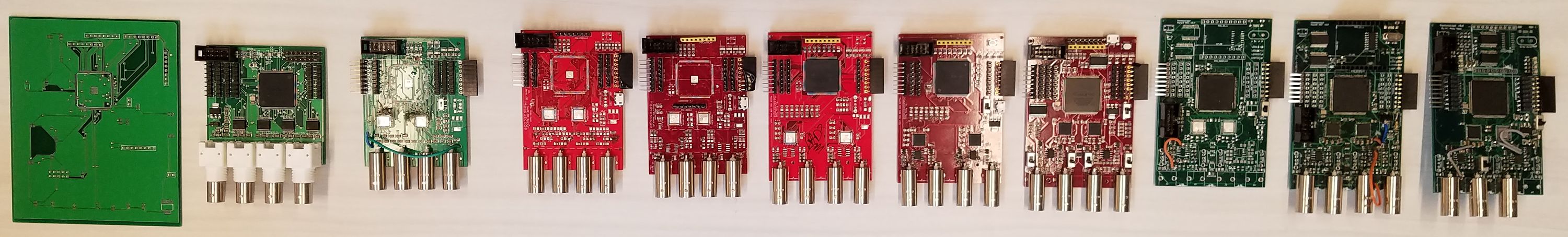
Starting way back in March, I made my first board:
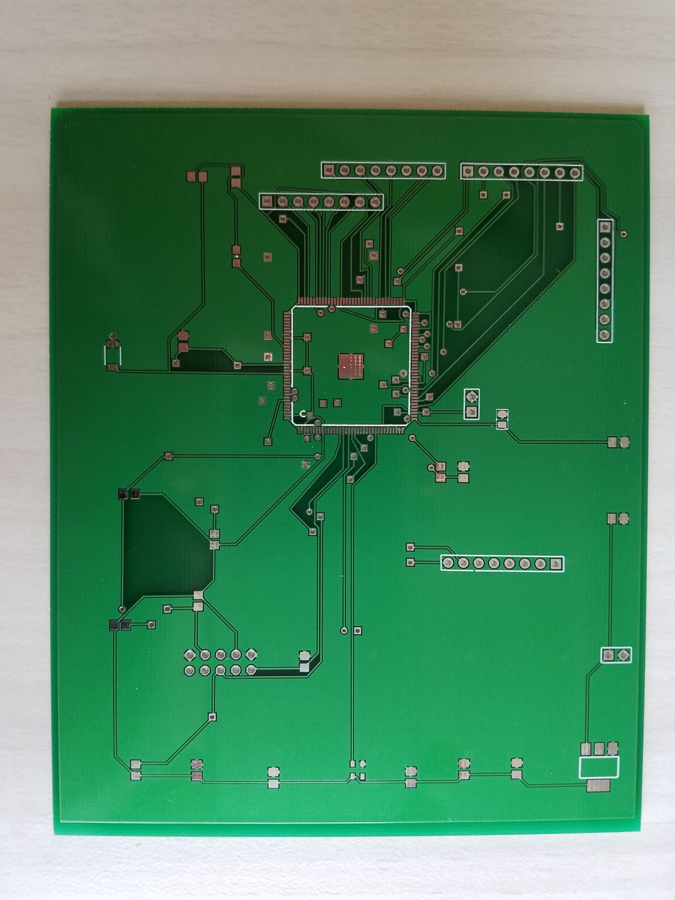
All it did was boot up the FPGA and have some lights you could blink. Still, it was a major achievement, and you can’t believe the sound I made when I first saw those lights blinking. (It also did some smoking first, I had the pins wrong on the 3.3V LDO!)
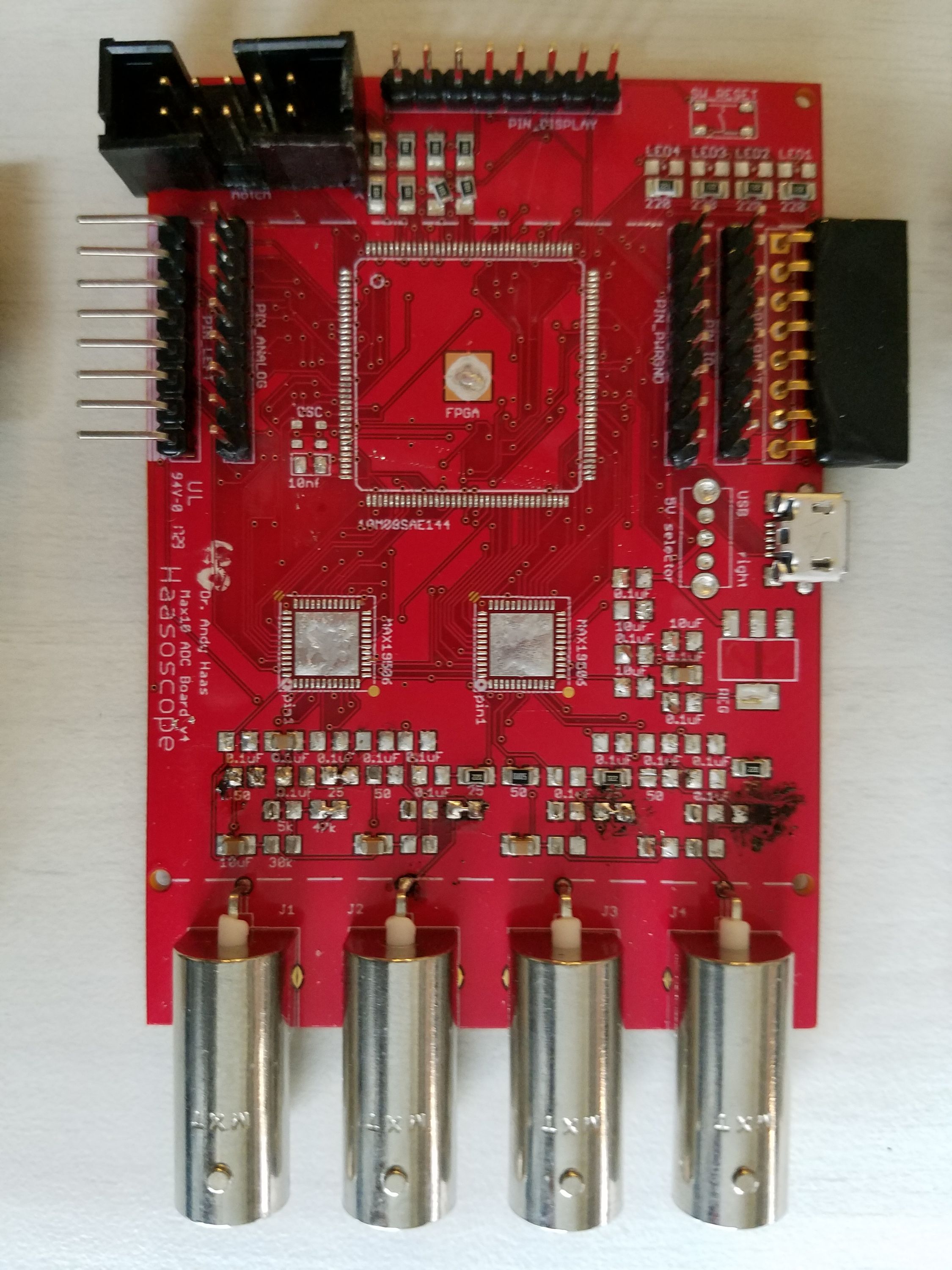
Then I added some ADCs, and BNC inputs, and things got serious quick - the Haasoscope was born!
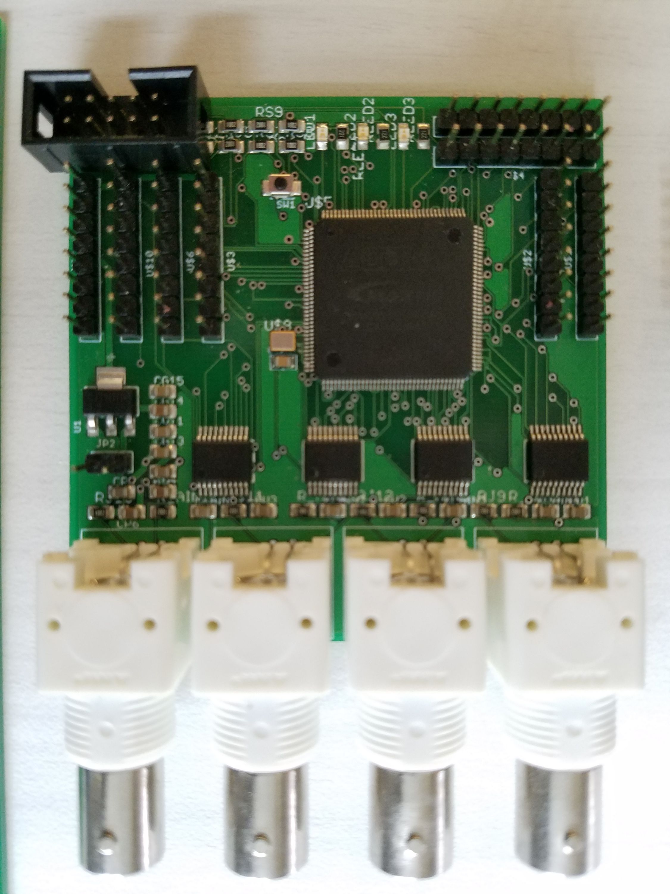
Then I switched to a cheaper and better ADC (dual channel), and started work on the "front end" that takes the analog signals and provides them to the ADC (this one had a 0-5V input range, I think):
(I forgot to power the digital outs of the ADCs, hence the extra wires.)
Oh, BTW, you may notice that many of these old boards are missing most of the their parts - that’s because I use many of the parts from old boards to make new ones!
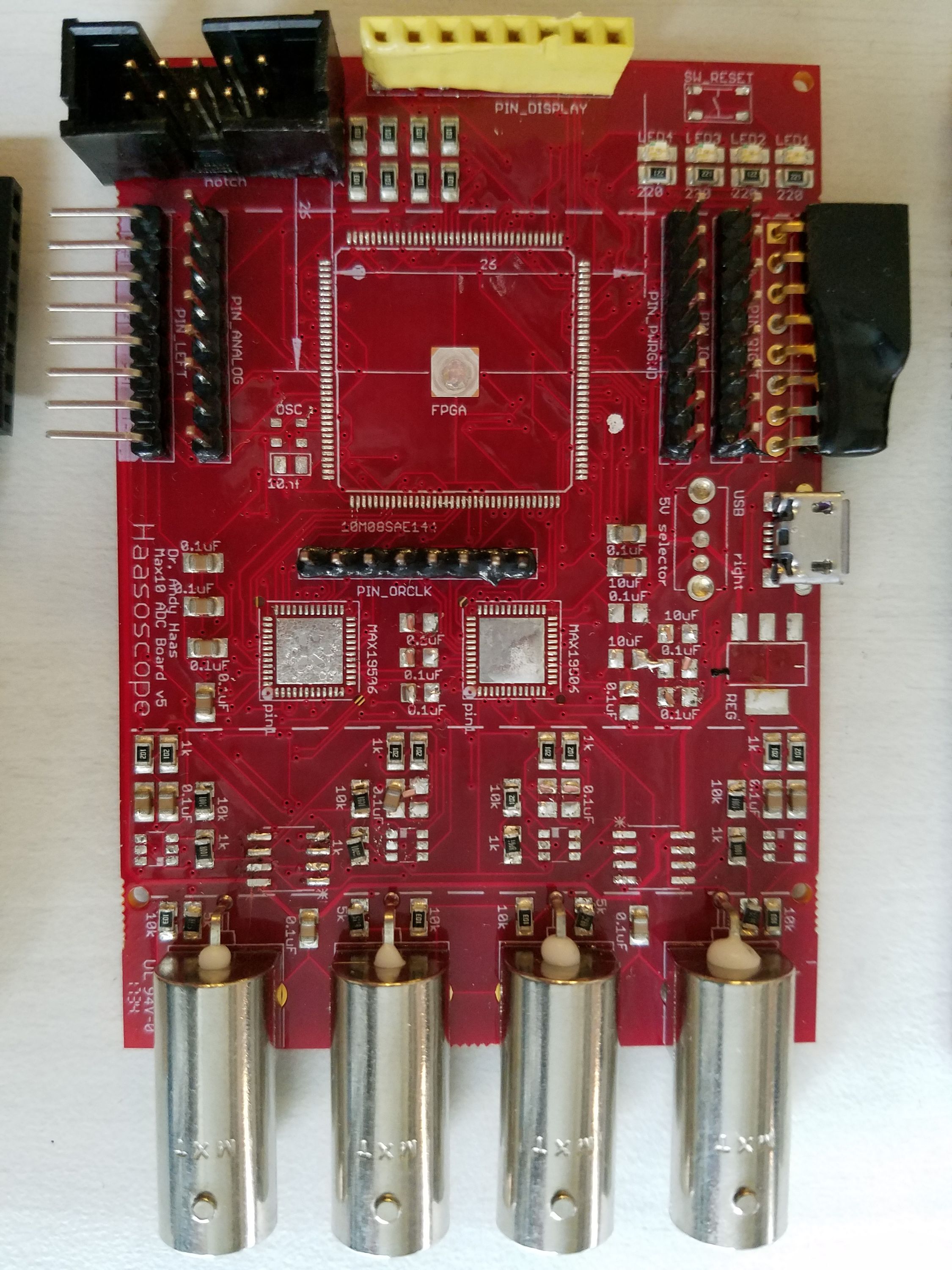
For board 4 I thought I was clever and could offset the input signals from -5 to 5V into 0-2V, using a voltage divider. I was wrong! (I’d forgotten about the input impedance of the ADCs!) So this round was largely a failure, but it gave it’s life for a good cause, my education!
v5 was more of a success. I bit the bullet and decided to add an op-amp for each channel, so I could do offset (and gain) properly. At first I used an op-amp that didn’t play nice with a single +5V supply (even though the datasheet seemed to say it would?!), but after I swapped in a MAX4416, success!
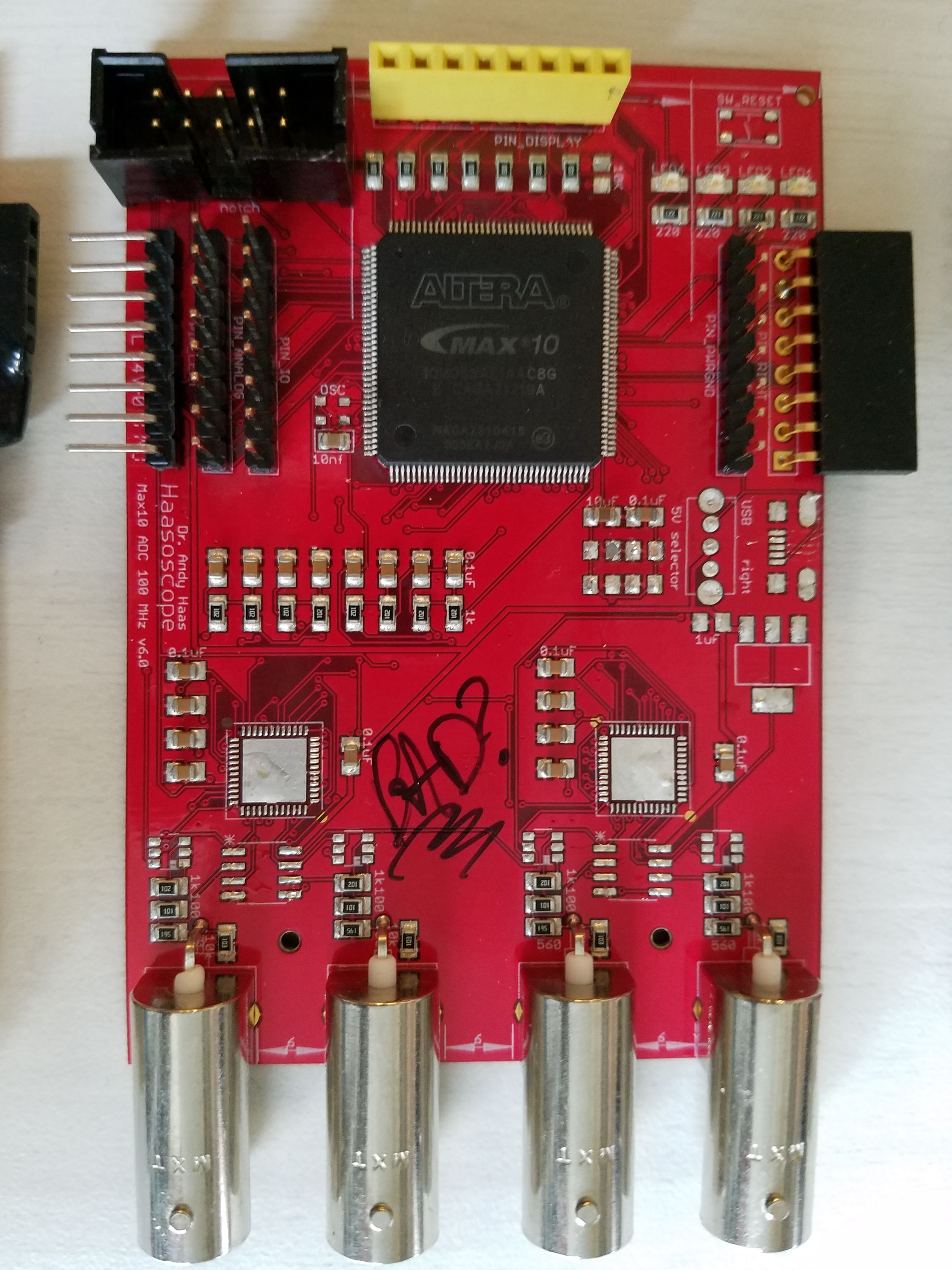
v6 implemented the fixed I learned I needed from v5, more or less worked OK. It says "bad?" because this one didn’t even boot up the FPGA, and I never figured out why (it wasn’t the clock, voltages, etc…). Fortunately I had ordered two of them, and it’s sister was fine!
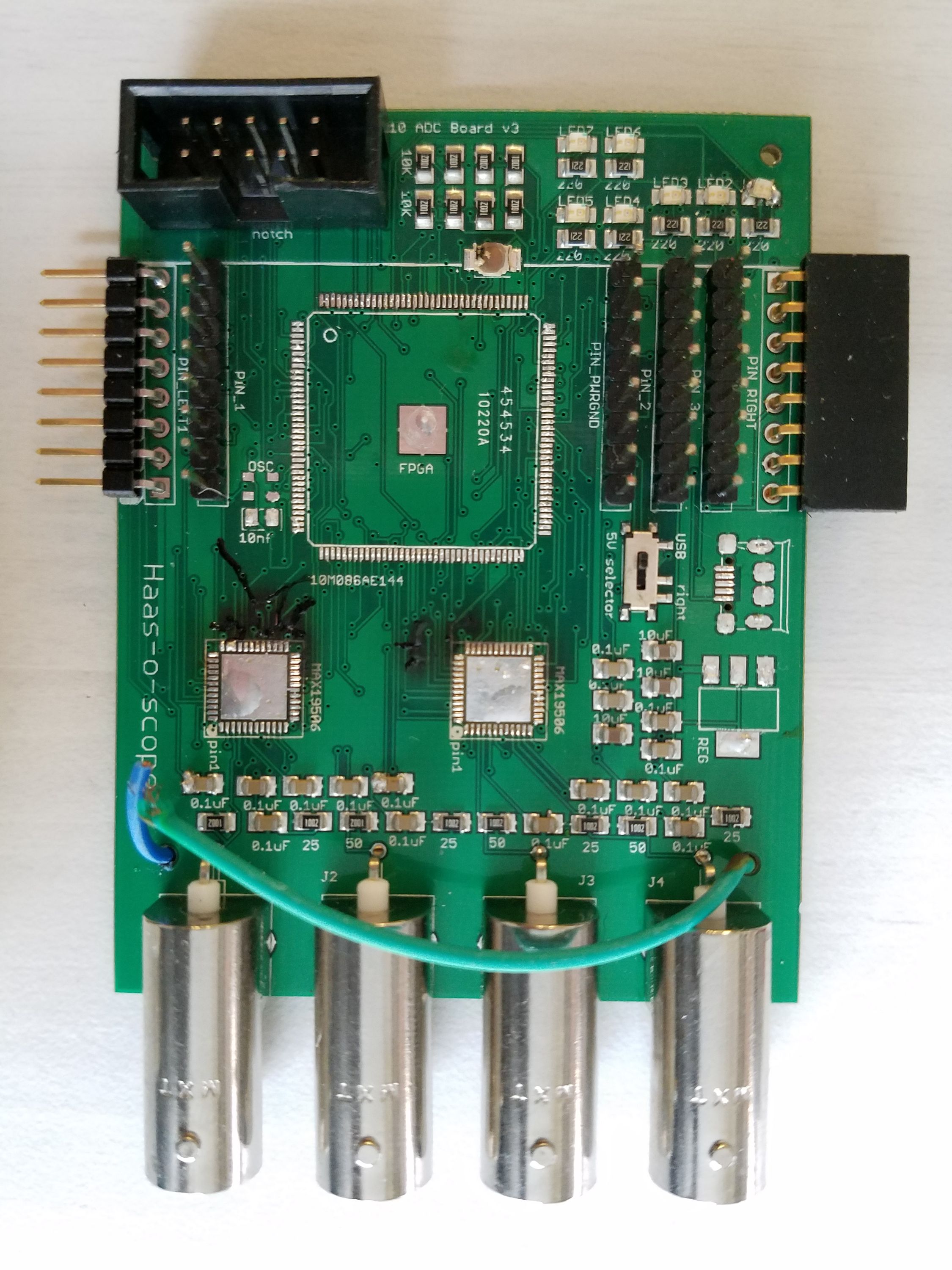
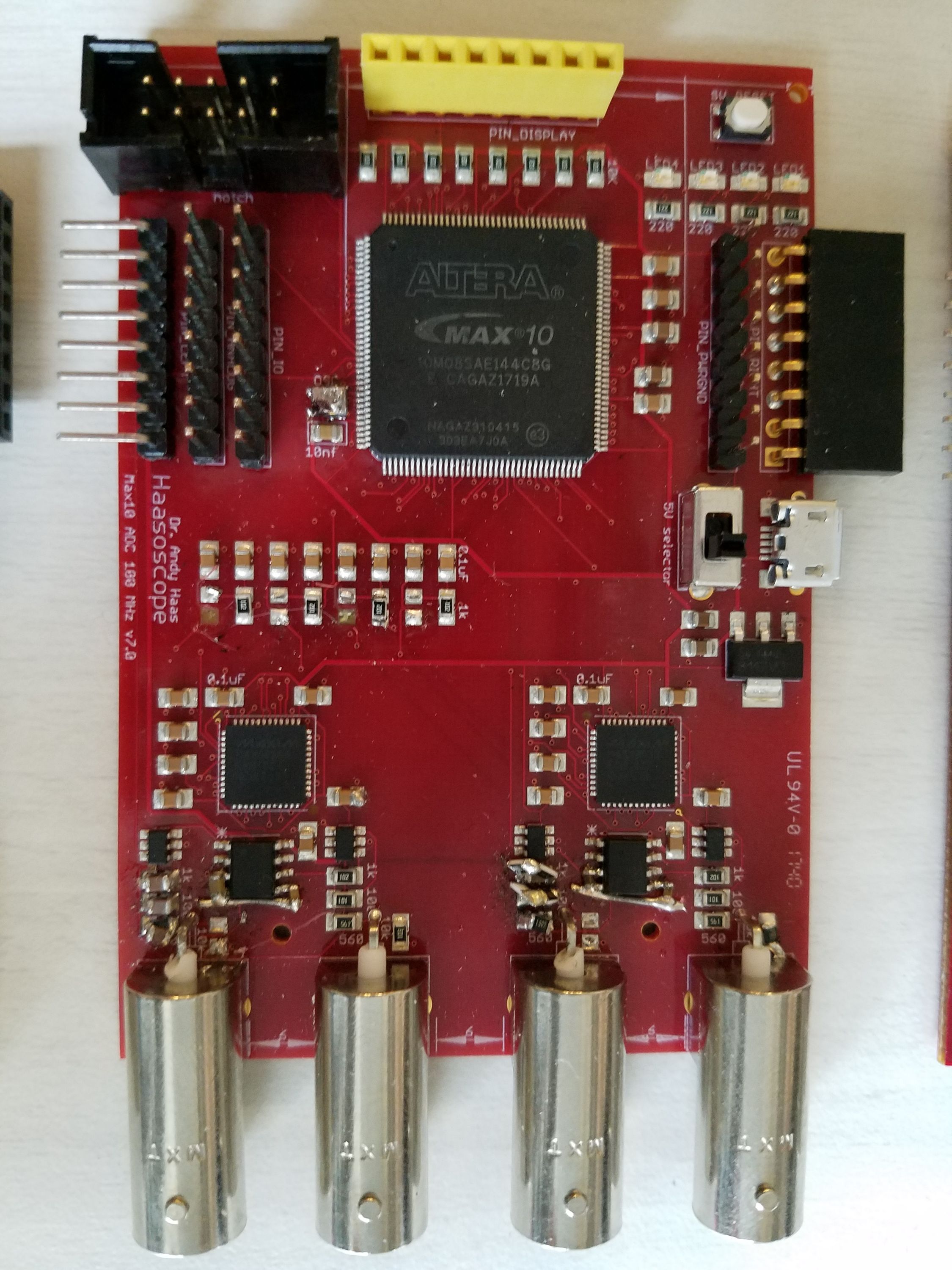
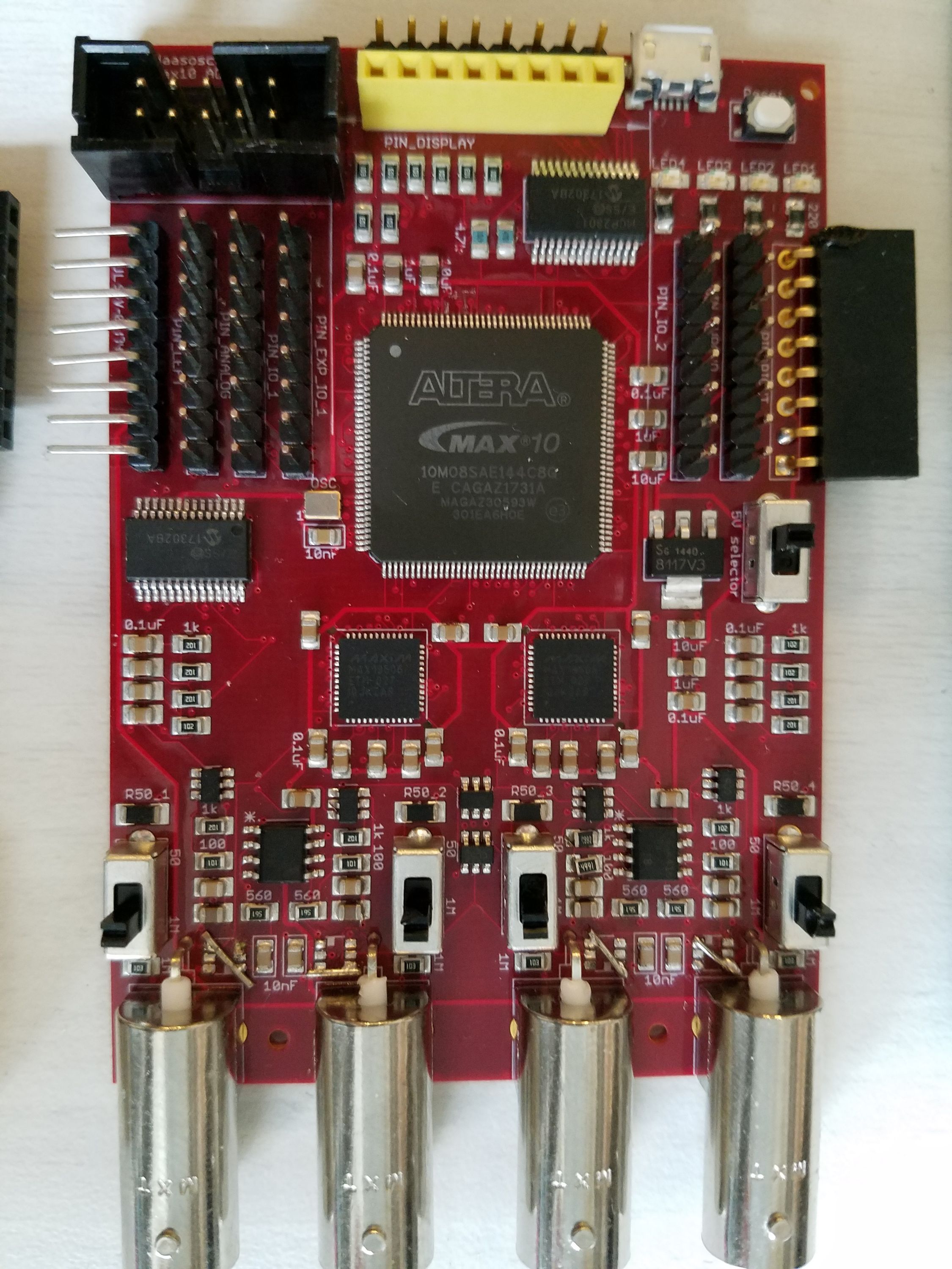
v7 is close to the modern Haasoscope. It had adjustable gain (low and high settings), and a (split) ground plane in a 4-layer PCB (which I later regretted and moved to a continuous ground plane). Macrofab accidentally rotated the 50 MHz oscillator though, which had a rough time fixing (see mess to the left of the FPGA)! Nowadays that would be a 30-second job for me, with a hot air gun. I also started playing around on this board with high-impedance inputs (so you don’t affect the circuit you’re measuring), at which point I had to worry about the capacitive reactance in the gain feedback loops, which dominate at high frequency. I don’t know if I invented it, but I discovered you can stack SMD resistors and capacitors on top of each other easily, if you want to add things in parallel! I was able to slap on the right capacitances in parallel with the resistors (see bottom left, for example):
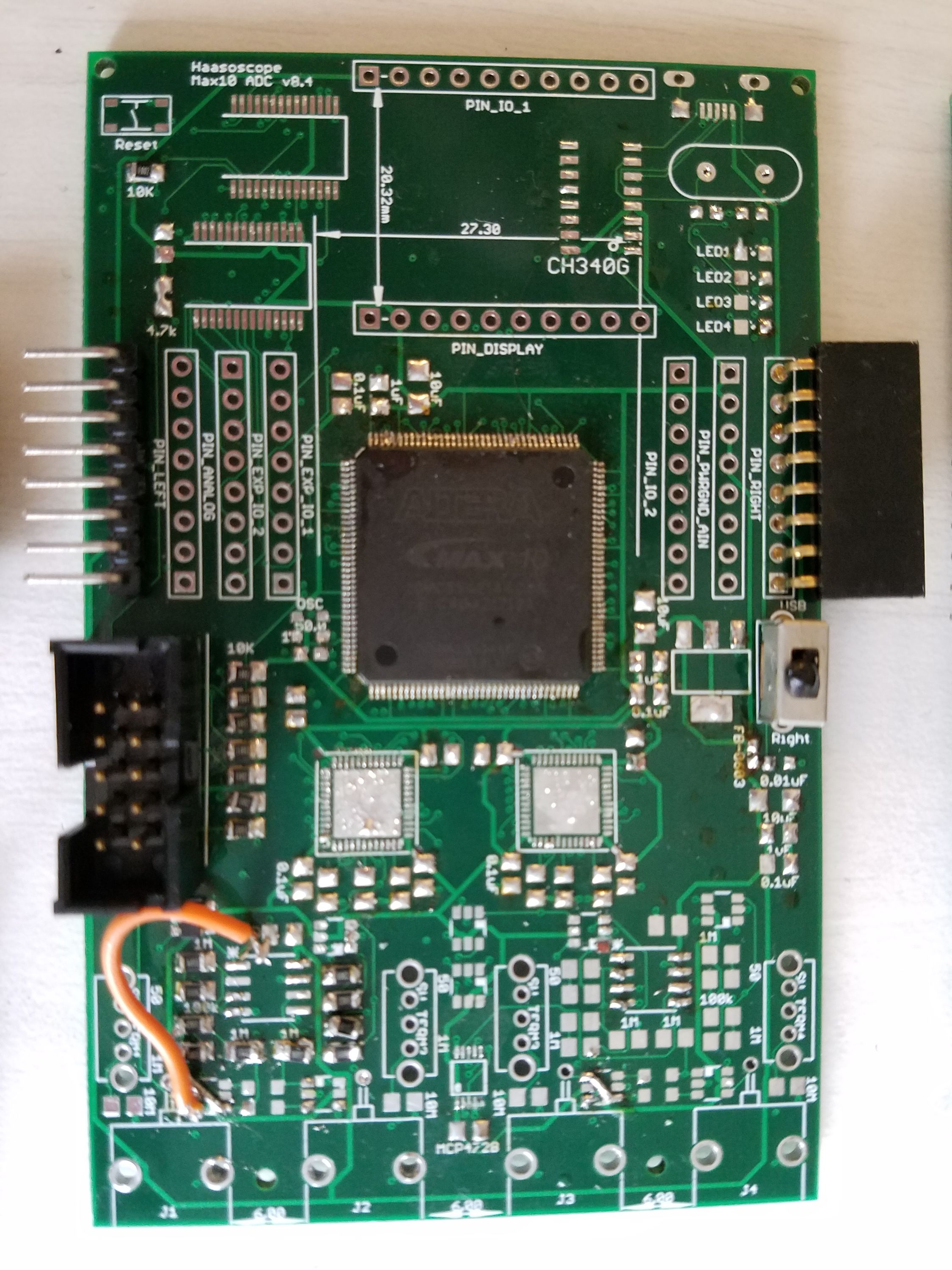
v8 really started to come together nicely. It fixed all the things I’d learned from v7, and added IO expanders (32 low speed GPIOs that you talk to over I2C - why waste high-speed FPGA pins on LEDs?!), a continuous ground plane (reduced inductive coupling), 50/IM Ohm termination, and oversampling (lets you duplicate channels 0/1 to 2/3 to double the sampling rate!). But the AC/DC coupling didn’t work at first - there wasn’t enough isolation using the analog switch. (I now use a solid-state relay.)
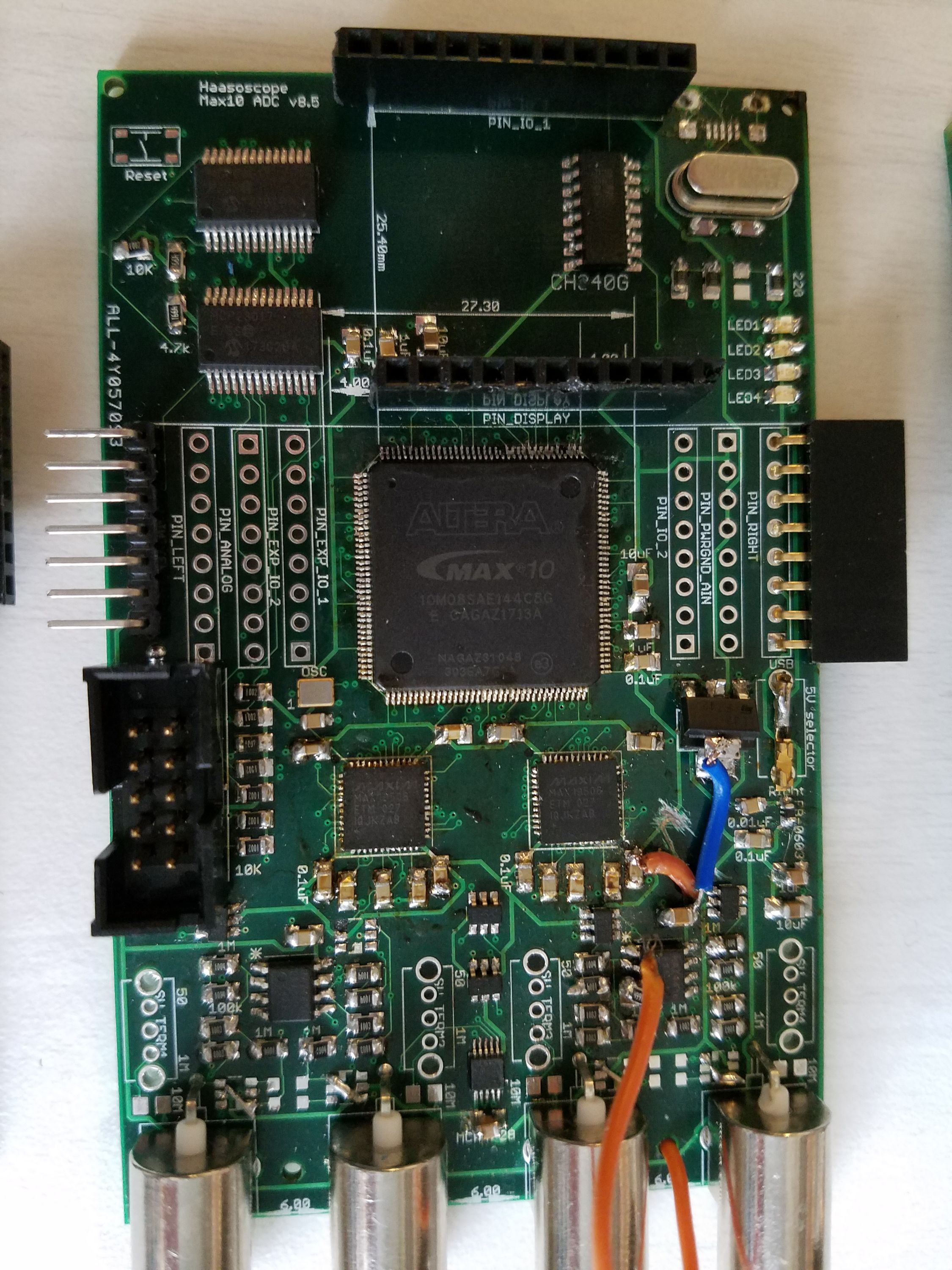
For v8.4 I was working on reducing noise. I moved to a 12-bit DAC for providing the offset voltages to the op-amps, instead of doing PWM using FPGA pins (what a dumb idea that was, in retrospect!). And I built in the USB-serial output, since it cost just 1$ and you almost always want it! I also made a set of IO pins at the top so you can plug on the USB2 board hat.
v8.5 is very close to 8.4, just from AllPCB instead of Seeed. I was testing them both - judgement, they’re both great, but AllPCB gives free shipping, so is almost half the cost! I also played around a bit with the 3.3V power distribution, as I was suspecting (correctly!) that some noise was still coming through on the power rails (hence the extra wires!).
v8.6 finally has working AC/DC coupling switches, using those SSRs! I also moved to powering the op-amps off 3.3V instead of directly from 5V - of course there’s less noise after the LDO, right?! I also added the "super-gain" mode (an extra factor of 100 in gain), which I talked about in a recent update. It messed things up at first though - I’d forgotten about the capacitance of the SSR (about 15pF!) I was using to switch into super-gain mode! I’ve moved to an old-fashioned physical switch now.
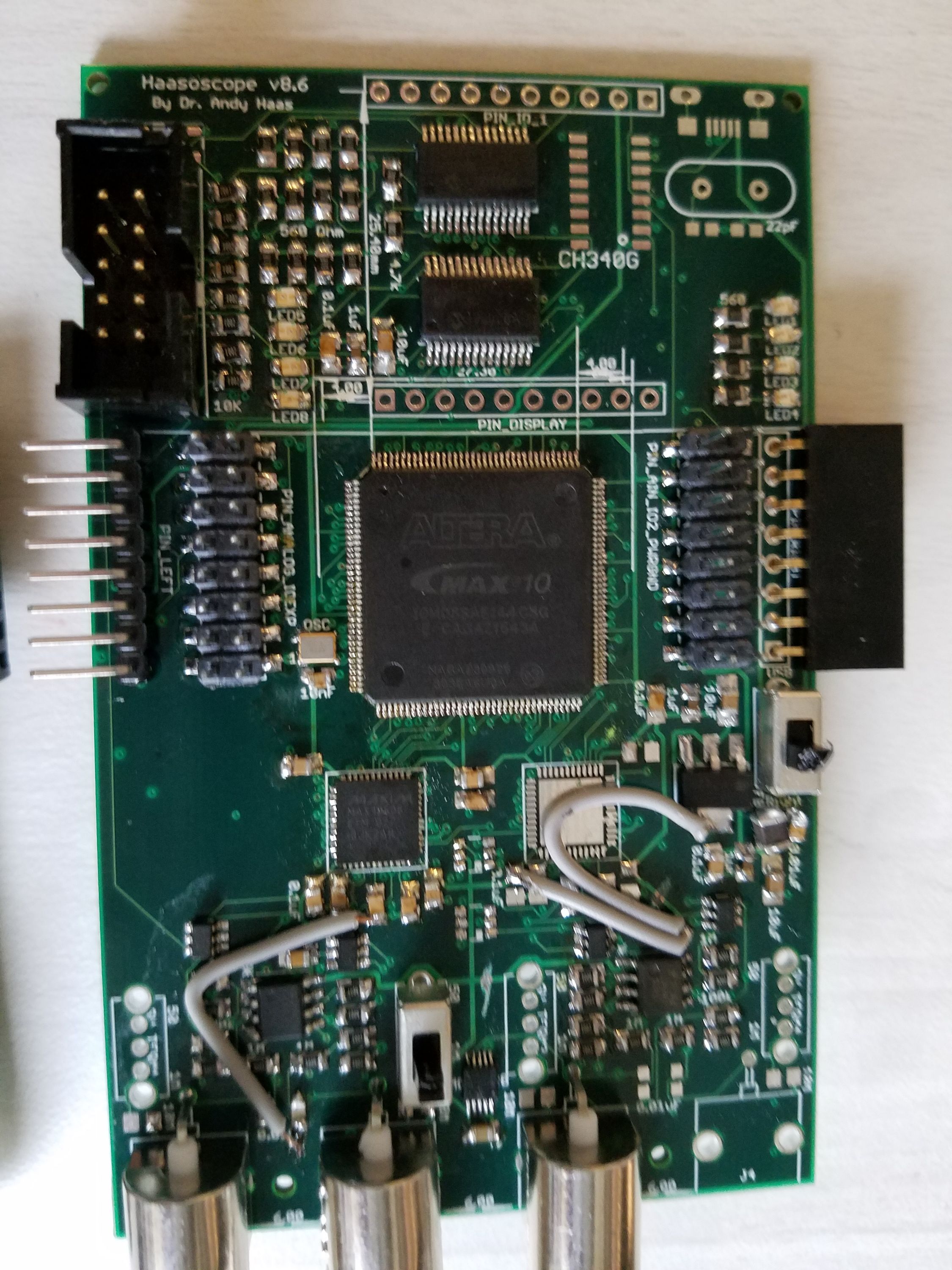
v8.7 is on the way! I’ll add a pic in the New Year. It’s going to have a separate 3.3V LDO for the analog part of the board, again to reduce noise, especially for that super-gain mode. (You can see I was testing that out in v8.5 - there’s 2 LDOs stacked on each other!) And I’ve added some variable capacitors to the inputs so I can fine-tune that reactance I was talking about. (I should do a separate update on that saga!) Oh, and I added an LED so you can tell if the board is on!
See you in 2018!